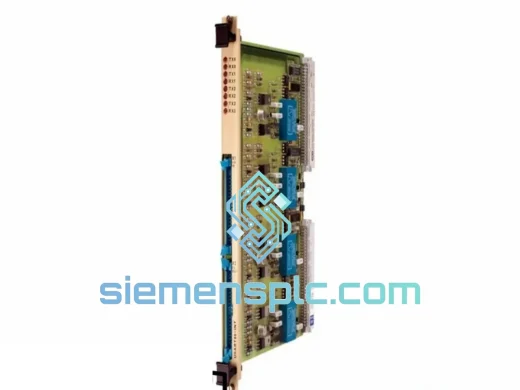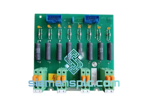
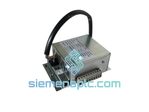
ABB
RFQ Ready
ABB 3BHB000272R0101 DCS I/O Interface Module
Symphony Plus
Origin SE
DCS I/O Interface Module
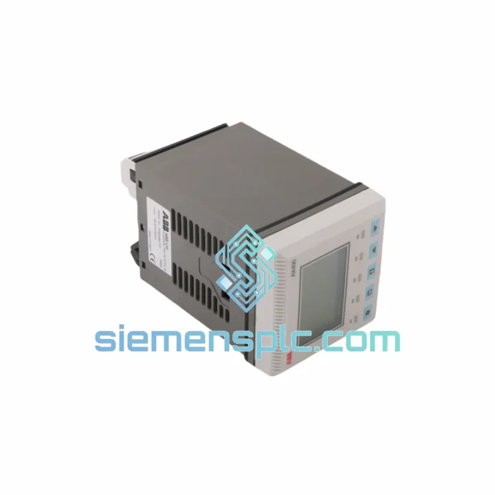
Request verified availability, condition, replacement risk review, packing options and courier lead time for AX410/50001.
Click Request Quote and the part number is inserted into the inquiry form automatically.
Core fields for model confirmation and RFQ routing. Detailed product narrative remains below.
The ABB AX410/50001 is a dual-channel analog input module engineered for deployment within ABB’s AX400 Series distributed control system platform. Its primary function is to acquire, condition, and digitize two independent field-level analog signals — typically 4–20 mA current loops or ±10 V voltage inputs — and transmit the processed values to the DCS controller via the AX400 backplane bus. In a control loop hierarchy, this module occupies the field interface layer: it is the first point at which raw physical process variables are converted into engineering-unit data that the controller can act upon.
Within a refinery column, a pharmaceutical batch reactor, or a power generation unit, the integrity of analog input acquisition directly determines the quality of closed-loop control. A 0.1% drift in a temperature or pressure reading at the input stage propagates through the PID algorithm and manifests as setpoint deviation at the final control element. The AX410/50001 addresses this by providing galvanically isolated, individually conditioned input channels with onboard signal validation — ensuring that the data presented to the controller reflects actual field conditions rather than cable-induced noise or ground-loop artifacts.
Real-time Stock & RFQ: [email protected] | WhatsApp: +86 18359268345
| Parameter | Specification |
|---|---|
| Part Number | AX410/50001 |
| Manufacturer | ABB |
| Series | AX400 Series |
| Module Function | Dual-Channel Analog Input |
| Number of Input Channels | 2 (independent, galvanically isolated) |
| Input Signal Types | 4–20 mA (current loop), ±10 V (voltage) |
| Resolution | 16-bit ADC per channel |
| Measurement Accuracy | ±0.1% of full scale (at 25 °C) |
| Channel-to-Channel Isolation | Galvanic isolation, ≥500 V DC |
| Channel-to-Backplane Isolation | Optical isolation (opto-coupler stage) |
| Sampling Rate | Configurable per channel; typical cycle ≤10 ms |
| Operating Temperature | 0 °C to +60 °C |
| Storage Temperature | -25 °C to +70 °C |
| Relative Humidity | 5–95% RH, non-condensing |
| Power Consumption | ≤3.5 W (from AX400 backplane rail) |
| EMC Compliance | EN 61000-4-2/3/4/5/6 (IEC 61000 series) |
| Backplane Interface | AX400 Series proprietary parallel bus |
| Compatible Controllers | ABB AC700F, AC800F (Freelance); S+ Controller (Symphony Plus) |
| Form Factor | Single-slot AX400 rack module |
| Weight | 680 g |
| Country of Origin | Germany |
| Warranty | 12 months from date of shipment |
The AX410/50001 implements a two-stage signal conditioning architecture per channel. At the field terminal, an input protection network — comprising transient voltage suppression (TVS) diodes and series current-limiting resistors — clamps surge events to within the ADC’s safe operating range. This is particularly relevant in installations where field wiring runs parallel to power cables or traverses areas with frequent switching transients from variable-frequency drives (VFDs) or motor starters.
Following the protection stage, each channel passes through an instrumentation amplifier with programmable gain, allowing the module to accept both low-level millivolt signals from thermocouples (via external transmitters) and full-range 4–20 mA loops without hardware modification. The amplifier’s common-mode rejection ratio (CMRR) exceeds 80 dB at 50/60 Hz, which is the primary mechanism by which the module suppresses power-frequency interference induced on long field cable runs.
The galvanic isolation barrier between the field-side analog circuitry and the backplane-side digital logic is implemented using opto-coupler technology rather than transformer-based isolation. This design choice eliminates the frequency-dependent impedance variation associated with transformer cores and provides a flat isolation characteristic from DC through the module’s full signal bandwidth. The isolation capacitance across the barrier is maintained below 50 pF, limiting high-frequency leakage current to levels compliant with IEC 61010-1 safety requirements.
On the digital side, a 16-bit successive-approximation register (SAR) ADC converts the conditioned analog signal. SAR topology is selected over delta-sigma for this application because it provides deterministic conversion time — a critical property in a DCS environment where the controller’s scan cycle must be able to predict exactly when a fresh input value will be available. The converted data is latched into a dual-port RAM buffer accessible by both the local module processor and the backplane bus interface logic, eliminating bus contention and ensuring that the controller always reads a complete, coherent sample rather than a partially updated value.
The module’s EMC design follows a layered approach: the PCB uses a four-layer stackup with dedicated ground planes separating analog and digital domains; all high-impedance analog traces are guarded by driven shield traces connected to the analog ground reference; and the module enclosure provides a Faraday cage effect that attenuates radiated emissions from the backplane bus clock lines. This architecture allows the AX410/50001 to maintain specified accuracy in environments with radiated field strengths up to 10 V/m (per IEC 61000-4-3 Level 3), which covers the majority of heavy industrial installation scenarios.
Every ABB AX410/50001 unit supplied by siemensplc.com is sourced through verified industrial supply channels with full part traceability. Prior to dispatch, each module undergoes a structured inspection protocol: physical examination of connector pins, label authenticity verification against ABB’s published part marking standards, and functional power-on verification where test equipment permits. Units are packed in anti-static (ESD) bags, placed in foam-lined cartons, and sealed with tamper-evident tape. For international shipments, moisture-barrier desiccant packs are included to protect against humidity exposure during transit.
Logistics operations are based in Xiamen, China — a major international port city with direct access to DHL Express, FedEx International Priority, and UPS Worldwide Express services. Standard export documentation — commercial invoice, packing list, and certificate of origin — is prepared for every shipment. For buyers in regions requiring import permits or end-user certificates, our logistics team provides advance documentation support to prevent customs clearance delays. Typical transit times are 3–5 business days to Europe and North America via express courier, and 5–8 business days to Southeast Asia, the Middle East, and South America.
All units are covered by a 12-month warranty from the date of shipment. Warranty claims are processed with a target response time of one business day. Defective units are replaced or credited at the buyer’s option, with return shipping costs covered by siemensplc.com for confirmed warranty cases.
Email: [email protected]
WhatsApp: +86 18359268345
Web: siemensplc.com
Location: Xiamen, China
© 2026 siemensplc.com. All rights reserved.
We check the full part number, brand, series and visible nameplate information before quotation.
Sales confirms stock path, condition option, quantity and realistic lead time for export dispatch.
DHL, FedEx, UPS or buyer courier arrangements can be reviewed with packing requirements.
Similar brand or category products for fast comparison and multi-item RFQ lists.