ABB
RFQ Ready
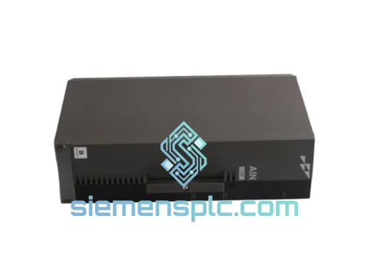
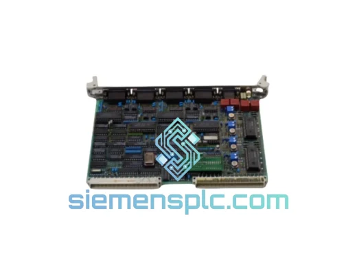
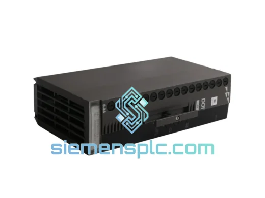
ABB P-HB-DOT-12010000 Safety Digital Output Module – AC500-S
AC500
Origin SE
Safety Digital Output Module
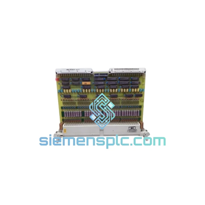
Request verified availability, condition, replacement risk review, packing options and courier lead time for GJR5143100R0001 35EK90.
Click Request Quote and the part number is inserted into the inquiry form automatically.
Core fields for model confirmation and RFQ routing. Detailed product narrative remains below.
The ABB GJR5143100R0001 (catalog alias 35EK90) is the bus coupler unit that anchors every S500 distributed I/O station to the AC500 fieldbus backbone. In a modular PLC topology, the CPU does not communicate directly with each I/O module; instead, it addresses a bus coupler that aggregates process data from all downstream I/O modules on the same station rail and presents a single, coherent process image to the fieldbus master. The GJR5143100R0001 performs exactly this function — it is the protocol translator, power distributor, and station supervisor rolled into one compact DIN-rail housing.
Within the AC500 S500 I/O architecture, the bus coupler connects to the fieldbus on its left-side interface and to the S500 I/O module bus on its right-side backplane connector. The internal station bus operates at a fixed clock rate, synchronizing data exchange between the coupler and up to 10 I/O modules per station. The coupler handles address assignment, module-type identification, and cyclic data mapping autonomously — reducing CPU overhead and ensuring deterministic scan-cycle behavior regardless of I/O station count.
Real-time Stock & RFQ: [email protected] | WhatsApp: +86 18359268345
| Parameter | Value |
|---|---|
| Part Number | GJR5143100R0001 |
| Catalog Reference | 35EK90 |
| Brand | ABB |
| Series | AC500 / S500 I/O |
| Module Function | Bus Coupler Unit (Fieldbus ↔ S500 I/O Station) |
| Station Bus Interface | Proprietary S500 backplane bus (right-side connector) |
| Max. I/O Modules per Station | Up to 10 S500 I/O modules |
| Supply Voltage | 24 V DC (–15% / +20%), supplied via terminal base |
| Current Consumption (internal logic) | Approx. 150 mA at 24 V DC |
| Station Bus Power Feed | Passes 24 V DC to downstream I/O modules via backplane |
| Ambient Operating Temperature | –25 °C to +60 °C |
| Storage Temperature | –40 °C to +70 °C |
| Relative Humidity | 5% to 95%, non-condensing |
| Protection Degree | IP20 (IEC 60529) |
| Mounting | DIN rail EN 60715 (35 mm) |
| Dimensions (W × H × D) | Approx. 45 mm × 100 mm × 75 mm |
| Weight | Approx. 300 g |
| EMC Compliance | EN 61000-6-2 (immunity), EN 61000-6-4 (emission) |
| Safety Standard | IEC 61131-2 |
| CE Marking | Yes |
| Country of Origin | Germany |
| Warranty | 12 months from date of shipment |
The GJR5143100R0001 implements a two-domain architecture that physically separates the fieldbus communication layer from the S500 station bus. This galvanic isolation boundary — enforced through optocoupler arrays on the fieldbus-side interface — prevents ground-loop currents and high-frequency transients originating on the fieldbus cable from propagating into the station bus and corrupting I/O data. In industrial environments where variable-frequency drives, contactors, and high-current switching loads generate conducted and radiated interference, this isolation boundary is not optional; it is the primary EMC defense mechanism of the entire I/O station.
On the station bus side, the coupler implements a master-slave polling protocol. The coupler acts as station master, issuing cyclic read/write commands to each I/O module slot in a fixed sequence. Each I/O module responds within a deterministic window, and the coupler assembles the complete process image before forwarding it to the fieldbus master in a single transaction. This architecture eliminates the variable latency that would result from the fieldbus master polling each I/O module individually — a critical advantage in time-sensitive control loops.
The module’s internal microcontroller manages three concurrent tasks: fieldbus protocol handling, station bus polling, and diagnostic data collection. Diagnostic registers capture per-module status flags including supply voltage deviation, wire-break detection (on supported I/O modules), and communication timeout events. These flags are mapped into the fieldbus process image as status bytes, making them directly readable by the AC500 CPU without requiring separate diagnostic communication cycles.
The backplane connector uses a gold-plated multi-point contact system rated for a minimum of 100 insertion cycles, maintaining contact resistance below 30 mΩ across the operating temperature range. This low-resistance path is essential for the 24 V DC power distribution function: the coupler feeds logic supply to all downstream I/O modules through the backplane, and any significant contact resistance would introduce voltage drop that could push marginal modules below their minimum operating voltage threshold.
Every GJR5143100R0001 unit supplied by siemensplc.com is sourced as genuine ABB original stock. ABB’s manufacturing process for AC500 S500 components applies IPC-A-610 Class 3 workmanship standards — the highest classification for electronic assemblies, covering solder joint integrity, component placement tolerances, and conformal coating requirements. Each unit carries ABB’s factory serial number and date code, providing full traceability back to the production batch.
Before dispatch from our Xiamen, China facility, each unit undergoes incoming inspection covering: label and serial number verification against ABB’s part numbering schema, visual inspection of the backplane connector contact surfaces and housing integrity, and continuity verification of the 24 V DC power input terminals. Units that do not pass inspection are quarantined and not shipped.
Logistics from Xiamen reach major industrial hubs on the following typical transit schedules: Hong Kong and Southeast Asia within 2–3 business days via air express; Europe (Frankfurt, Amsterdam, Rotterdam) within 4–6 business days via DHL Express or FedEx International Priority; North America (Los Angeles, Chicago, New York) within 5–7 business days; Middle East and South Asia within 3–5 business days. All shipments include commercial invoice, packing list, and certificate of origin. Export classification and HS code documentation are prepared for each shipment to facilitate customs clearance without delay.
A 12-month warranty covers all units against manufacturing defects and functional failure under normal operating conditions. Warranty claims are processed with a target response time of 48 hours from receipt of the defective unit.
Email: [email protected]
WhatsApp: +86 18359268345
Web: siemensplc.com
Location: Xiamen, China
© 2026 siemensplc.com. All rights reserved.
We check the full part number, brand, series and visible nameplate information before quotation.
Sales confirms stock path, condition option, quantity and realistic lead time for export dispatch.
DHL, FedEx, UPS or buyer courier arrangements can be reviewed with packing requirements.
Similar brand or category products for fast comparison and multi-item RFQ lists.