ABB
In Stock OK
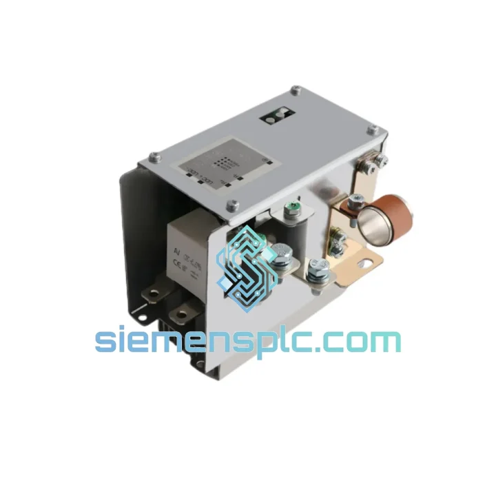
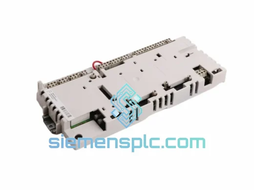
ABB NBRA-656C Brake Chopper Module – DCS800 Series
Request verified availability, condition, replacement risk review, packing options and courier lead time for NBRA-656C.
BrandABB
Part NumberNBRA-656C
ConditionAvailability Check
Lead TimeRFQ Confirmation
DocumentsDatasheet / photos by RFQ
ShippingExport packing available
Auto-filled RFQ
NBRA-656C
Click Request Quote and the part number is inserted into the inquiry form automatically.
- Reply by email: [email protected]
- WhatsApp / Tel: +86 18359268345
- Mon-Sat 9:00-18:00 GMT+8
Procurement Data
Key Product Information
Core fields for model confirmation and RFQ routing. Detailed product narrative remains below.
- Brand
- ABB
- Primary Part Number
- NBRA-656C
- Product Type
- Brake Chopper Module
- Series / Family
- S800
- Manufacturer
- ABB Ltd.
- Country of Origin
- SE
- Catalog Category
- Motor Drives
- Warranty
- 12 months from confirmed shipment date
Model confirmed for inquiry
NBRA-656C
Send quantity, destination and urgency. The RFQ form keeps this part number attached.
Request Quote
Product Overview
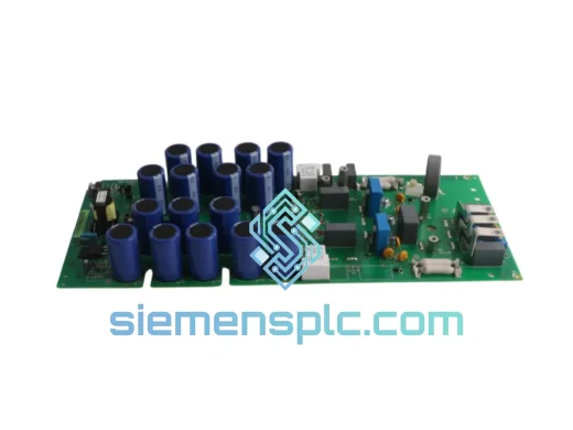
ABB NBRA-656C: DC Bus Overvoltage Suppression via Controlled Resistive Dissipation in DCS800 Thyristor Drive Systems
The NBRA-656C is a factory-designed brake chopper module for ABB’s DCS800 thyristor DC drive platform. Its function is singular and non-negotiable in high-inertia drive applications: intercept regenerative energy accumulating on the DC bus during deceleration transients and divert it through an external braking resistor before the bus voltage climbs into the drive’s hardware overvoltage protection band. This is not a retrofit accessory — it is an integral component of the DCS800’s energy management architecture, mechanically and electrically matched to the drive’s internal bus bar geometry and thermal infrastructure.
In single-quadrant thyristor rectifier topologies, the power bridge conducts current in one direction only. When a mechanically loaded motor transitions from motoring to generating — as occurs during controlled deceleration of a paper machine roll, a mine hoist drum, or a steel strip tension reel — the armature back-EMF drives current back toward the DC bus. The bus capacitance absorbs this energy, and the bus voltage rises at a rate governed by the regenerated power and the total capacitance on the rail. Left unmanaged, this voltage rise trips the drive’s overvoltage fault, halting the deceleration sequence and leaving the mechanical load to coast — an outcome that is operationally unacceptable in most process industries.
The NBRA-656C resolves this by placing an IGBT-switched dissipation path directly across the DC bus. The moment the measured bus voltage crosses a defined threshold, the module’s gate drive circuit saturates the IGBT, completing the circuit through the external braking resistor. The resistor converts the regenerated electrical energy to heat at a rate determined by its resistance value and the instantaneous bus voltage. When the bus voltage drops back below the hysteresis lower limit, the IGBT turns off, and the resistor is disconnected. This cycle repeats as needed throughout the deceleration ramp, maintaining the bus voltage within the drive’s safe operating window without any intervention from the supervisory control layer.
The module mounts directly to the DCS800’s internal bus bar structure, sharing the drive’s heatsink and thermal management path. Its operational status — active braking, fault condition, or standby — is reported through the DCS800’s native diagnostic word, accessible to the supervisory PLC over any fieldbus interface the drive supports. No additional I/O wiring, no separate communication module, no external monitoring relay is required.
Real-time Stock & RFQ: [email protected] | WhatsApp: +86 18359268345
Technical Parameters
| Parameter | Specification |
|---|---|
| Part Number | NBRA-656C |
| Manufacturer | ABB Ltd. |
| Compatible Drive Platform | DCS800 DC Drive Series — all frame sizes |
| Module Function | DC Bus Brake Chopper / Regenerative Energy Dissipation |
| Primary Switching Device | High-voltage IGBT with integrated gate drive circuit |
| Bus Voltage Sensing | Precision resistive divider, continuous real-time measurement |
| Overvoltage Activation Threshold | Parameterizable via DCS800 drive parameter set |
| Hysteresis Band | Built-in comparator hysteresis; prevents IGBT high-frequency chattering at threshold boundary |
| Braking Resistor Interface | External terminal block; resistor value and power rating selected per application inertia and duty cycle |
| Galvanic Isolation | Optocoupler isolation between gate drive stage and control/monitoring logic |
| Mounting Method | Direct bus bar mount inside DCS800 drive cabinet; shared heatsink thermal path |
| Operating Temperature Range | −15 °C to +40 °C (derate above 40 °C per DCS800 hardware manual) |
| Module Weight | 2,160 g |
| Country of Origin | Germany |
| Warranty | 12 months from confirmed shipment date |
Hardware Logical Analysis
The NBRA-656C’s switching topology is built around a single high-voltage IGBT whose collector-emitter path bridges the DC bus positive rail and the external braking resistor terminal. The gate drive circuit continuously samples the DC bus voltage through a precision resistive divider network. This sampled voltage feeds a comparator stage referenced against a threshold value — either factory-fixed or adjusted through the DCS800 parameter interface. When the comparator output crosses the threshold, the gate drive applies a controlled gate-emitter voltage, saturating the IGBT within microseconds and completing the resistor dissipation circuit.
A hysteresis window embedded in the comparator logic prevents the IGBT from toggling at high frequency when the bus voltage oscillates near the threshold boundary. Without this hysteresis, marginal overvoltage conditions would cause rapid on-off cycling, accumulating thermal stress on the IGBT junction at a rate that would degrade long-term device reliability. The hysteresis band is sized to ensure each switching event transfers a meaningful energy quantum to the resistor while keeping the bus voltage within the drive’s continuous safe operating area.
Galvanic isolation between the high-voltage gate drive stage and the low-voltage control circuitry is implemented via optocouplers. This isolation barrier blocks common-mode transients — generated by IGBT switching edges, thyristor commutation events, and external contactor operations on the same bus — from coupling into the DCS800’s control board. The isolation withstand voltage is specified to exceed the peak DC bus voltage by a margin consistent with IEC 61800-5-1 reinforced insulation requirements for variable-speed drive systems.
PCB layout follows established power electronics EMC discipline: the high-current switching loop — IGBT collector, bus bar connection, resistor terminal, and return path — is minimized in enclosed area to reduce stray inductance. Residual stray inductance would otherwise generate collector-emitter voltage spikes at IGBT turn-off, potentially exceeding the device’s rated breakdown voltage. Snubber networks placed directly across the IGBT terminals clamp these spikes within the device’s safe operating area. The analog measurement and comparator circuitry is physically separated from the switching loop, with a segmented ground plane preventing high-frequency switching currents from injecting noise into the voltage measurement path and causing false threshold crossings.
Thermal coupling to the DCS800 heatsink is achieved through a controlled-torque mounting interface with factory-applied thermal interface material. The IGBT junction-to-case thermal resistance, combined with the case-to-heatsink interface resistance, determines the maximum continuous braking duty cycle at a given ambient temperature. ABB’s DCS800 hardware manual provides the full thermal derating curves, enabling system engineers to verify braking duty cycle compliance before commissioning without empirical testing.
System Integration Benefits
- Sub-10 µs Overvoltage Response: The IGBT gate drive reacts to bus overvoltage within the comparator propagation delay — typically under 10 µs — preventing the bus voltage from reaching the drive’s hardware overvoltage protection threshold and eliminating unplanned production stops caused by deceleration-induced bus excursions.
- Zero Supplementary Wiring: Module status is reported through the DCS800’s existing diagnostic word bits, readable by the supervisory PLC over the drive’s standard fieldbus interface — PROFIBUS-DP, DeviceNet, or Modbus RTU — without any additional field wiring, I/O modules, or communication adapters.
- Parameterized Threshold Adjustment: The overvoltage activation threshold is configurable through the DCS800’s parameter set, allowing the same hardware to serve different DC bus voltage ratings and different load deceleration profiles without physical modification to the module or its wiring.
- Mechanical Brake Wear Reduction: Absorbing deceleration energy electrically reduces the frequency and duration of mechanical brake engagement on hoist, crane, and winder applications, extending friction material service intervals and reducing unplanned maintenance downtime in continuous-process environments.
- Resistor Thermal Monitoring via Drive Analog Input: An external thermistor mounted on the braking resistor can be wired to the DCS800’s analog input, enabling real-time resistor temperature monitoring through the drive’s parameter display and event logging — providing a pre-alarm before resistor overtemperature causes a fault trip.
- Resistor-Scalable Braking Power: Braking power capacity is determined by the external resistor’s resistance value and continuous power rating, not by the NBRA-656C itself. This allows the braking system to be scaled for different load inertia values by substituting only the resistor, preserving the capital investment in the chopper module across multiple application variants.
- Compact Internal Mounting Eliminates External Enclosure: Direct bus bar installation inside the DCS800 cabinet removes the need for a separate external braking unit enclosure, eliminating inter-enclosure cable runs, IP-rated enclosure costs, cable gland hardware, and the associated installation labor from the project BOM.
- Braking Event Data for Predictive Maintenance: Braking event frequency and duration, logged through the DCS800’s event buffer, provide quantitative data on load deceleration behavior over time. Trends in braking activity can indicate changes in load inertia, mechanical coupling wear, or process parameter drift before these conditions manifest as drive faults or unplanned stops.
- Deterministic Deceleration Ramp Execution: By maintaining the DC bus voltage within bounds throughout the deceleration ramp, the NBRA-656C ensures the drive’s speed regulator operates on a stable voltage rail, preserving the accuracy of the deceleration time constant and preventing ramp overshoot caused by bus voltage-induced current limit intervention.
Quality Assurance & Global Logistics
NBRA-656C units held in our Xiamen inventory are sourced through ABB’s authorized distribution channels and verified OEM surplus pipelines with full traceability documentation. Each unit is inspected on receipt against ABB’s part labeling and packaging standards, and stored under ESD-controlled conditions to protect the IGBT gate oxide layer and optocoupler devices from electrostatic damage during storage.
Pre-shipment inspection covers physical integrity of the PCB assembly, IGBT device, bus bar connection terminals, and external resistor terminals; label authenticity verification against ABB’s part number and date code conventions; and gate drive circuit continuity checks where test access permits. Units that do not pass inspection criteria are quarantined and withheld from dispatch.
Export packaging is engineered for international freight handling: anti-static inner bag, closed-cell foam insert profiled to the module’s geometry, single-wall inner carton, and double-wall outer carton rated for air freight drop and compression loads per ISTA 2A. Sea freight consignments receive additional moisture-barrier packaging with silica gel desiccant. All export documentation — commercial invoice, packing list, HS code classification, and certificate of origin — is prepared for each shipment to facilitate customs clearance at destination.
Xiamen’s logistics infrastructure supports same-day dispatch on orders confirmed before 14:00 CST. Air freight transit benchmarks from Xiamen Gaoqi International Airport: Frankfurt 3–4 business days, Houston 4–5 business days, Singapore 2–3 business days, Dubai 3–4 business days. DHL Express, FedEx International Priority, and UPS Worldwide Express options are available for time-critical requirements. Tracking numbers are issued within 24 hours of dispatch. Incoterms supported: EXW, DAP, and DDP — selected based on buyer preference and destination import duty requirements. Transit insurance is available on request for high-value consignments.
The 12-month warranty covers component failure and manufacturing defects under operating conditions within ABB’s DCS800 hardware specification limits. Warranty replacement units are dispatched within 5 business days of confirmed fault diagnosis and return authorization.
Contact Information
Email: [email protected]
WhatsApp: +86 18359268345
Web: siemensplc.com
Location: Xiamen, China
© 2026. All rights reserved.
Ready to quote
[email protected]
Send This Part Number to Sales
RFQ workflow
Quality workflow ->
Confirmation Process
01Model confirmation
We check the full part number, brand, series and visible nameplate information before quotation.
02Availability reply
Sales confirms stock path, condition option, quantity and realistic lead time for export dispatch.
03Packing & courier
DHL, FedEx, UPS or buyer courier arrangements can be reviewed with packing requirements.
Continue sourcing
Browse full catalog ->
Related Automation Parts
Similar brand or category products for fast comparison and multi-item RFQ lists.
ABB
RFQ Ready
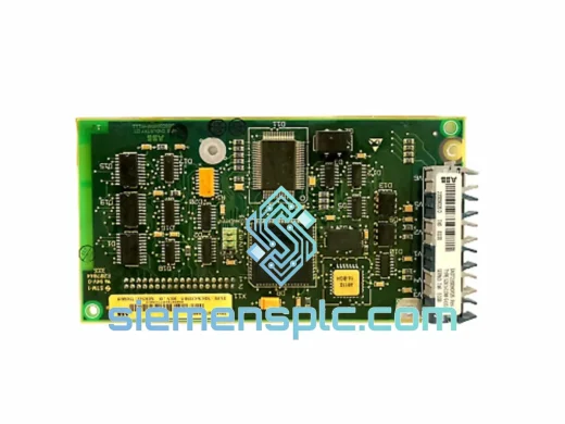
ABB SDCS-COM-5 3BSE006567R1 Fieldbus Communication Module
S800
Origin SE
Fieldbus Communication Module
ABB
RFQ Ready
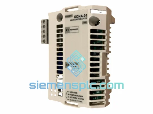
ABB RDNA-01 DeviceNet Adapter Module – ACS800 ACS600
S800
Origin SE
Fieldbus Communication Module
ABB
RFQ Ready
ABB RDCU-12C 3AUA0000036521 Drive Control Unit
S800
Origin SE
PLC & Drive Control Module