
ABB
In Stock OK
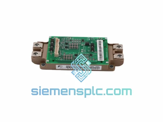
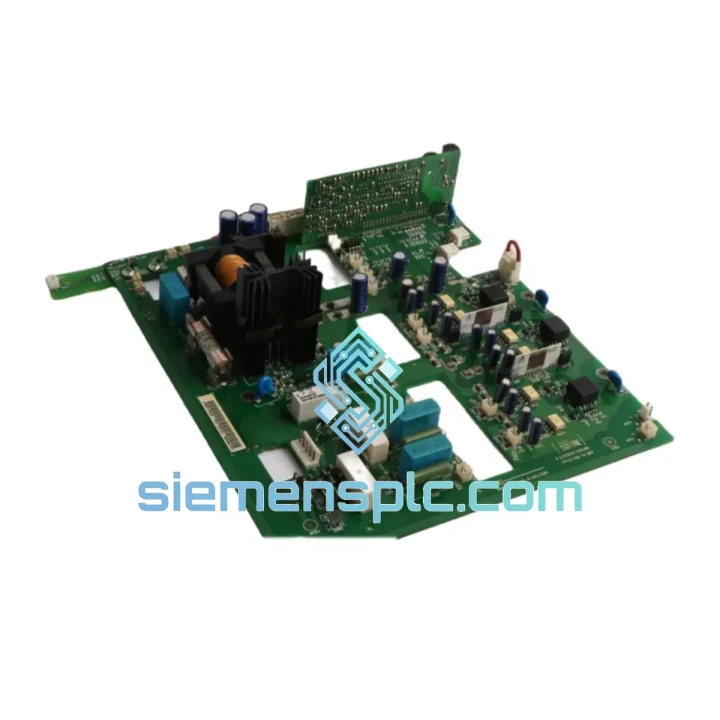
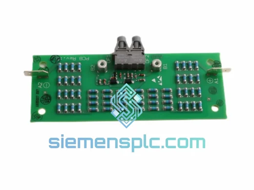
ABB RINT-6621C 6830691F Gate Drive Interface Board – RINT Series
Request verified availability, condition, replacement risk review, packing options and courier lead time for RINT-6621C.
BrandABB
Part NumberRINT-6621C
ConditionAvailability Check
Lead TimeRFQ Confirmation
DocumentsDatasheet / photos by RFQ
ShippingExport packing available
Auto-filled RFQ
RINT-6621C
Click Request Quote and the part number is inserted into the inquiry form automatically.
- Reply by email: [email protected]
- WhatsApp / Tel: +86 18359268345
- Mon-Sat 9:00-18:00 GMT+8
Procurement Data
Key Product Information
Core fields for model confirmation and RFQ routing. Detailed product narrative remains below.
- Brand
- ABB
- Primary Part Number
- RINT-6621C
- Product Type
- Gate Drive Interface Board
- Series / Family
- S800
- Manufacturer
- ABB Ltd.
- Country of Origin
- SE
- Catalog Category
- Motor Drives
- Warranty
- 12 months against manufacturing defects from date of shipment
Model confirmed for inquiry
RINT-6621C
Send quantity, destination and urgency. The RFQ form keeps this part number attached.
Request Quote
Product Overview
ABB RINT-6621C 6830691F — Optically Isolated Gate Drive Interface Board for ACS800 High-Power Variable Frequency Drives
The ABB RINT-6621C (order reference: 6830691F) is a purpose-engineered gate drive interface board occupying the signal boundary between the RMIO main control board and the IGBT power module assembly within ABB’s ACS800 multi-drive and single-drive platforms. Its primary function is bidirectional: it translates 5 V logic-level PWM firing commands from the control layer into ±15 V DC bipolar gate pulses capable of driving high-power IGBT modules into and out of saturation with sub-microsecond precision, while simultaneously returning discrete fault status signals — desaturation events, gate supply undervoltage, and fiber link integrity — back to the supervisory control layer. This dual-direction signal architecture is what enables closed-loop motor control determinism in continuous-duty industrial processes where unplanned downtime carries measurable production cost.
The board’s physical architecture reflects ABB’s internal design rules for IEC 61800-3 Category C3 electromagnetic environments. High-voltage gate drive traces are routed on inner PCB layers, separated from low-voltage logic signal planes by dedicated copper ground pours, reducing capacitive cross-coupling below the threshold that would introduce timing jitter into IGBT switching edges. The result is gate pulse edge consistency across all six channels within ±50 ns — a specification that directly determines DC bus voltage ripple amplitude in three-phase inverter topologies.
Real-time Stock & RFQ: [email protected] | WhatsApp: +86 18359268345
Technical Parameters
| Parameter | Specification |
|---|---|
| Part Number | RINT-6621C |
| Order Reference Code | 6830691F |
| Manufacturer | ABB Ltd. |
| Product Series | RINT (Drive Interface Board Series) |
| Board Function | IGBT Gate Drive Interface / Optical Isolation Module |
| Compatible Drive Platform | ABB ACS800 Series (single-drive and multi-drive cabinet configurations) |
| Logic Supply Voltage (Input) | +5 V DC, sourced from RMIO/RDCO control board backplane connector |
| Gate Drive Output Voltage | +15 V DC (turn-on) / −15 V DC (active turn-off clamp) |
| Isolation Technology | High-speed opto-coupler, galvanic isolation gate-to-logic side |
| CMTI Rating (Opto-coupler) | ≥15 kV/µs common-mode transient immunity |
| Gate Pulse Propagation Delay | <1 µs per channel (matched ±50 ns across all 6 channels) |
| Signal Interface to Control Board | PCB ribbon connector + fiber optic link (DDCS compatible) |
| Desaturation Detection | V_CE(sat) monitoring per channel; soft-shutdown ramp ≈2–5 µs |
| Operating Ambient Temperature | 0 °C to +50 °C (drive cabinet installed) |
| Storage Temperature | −40 °C to +70 °C |
| Relative Humidity | 5–95% RH, non-condensing (IEC 60068-2-78) |
| Vibration Resistance | IEC 60068-2-6: 2–9 Hz / 3.5 mm displacement; 9–200 Hz / 10 m/s² |
| PCB Construction | 4-layer minimum, FR4, dedicated power and signal ground planes |
| Thermal Monitoring Output | NTC thermistor signal to ACS800 thermal model firmware |
| Compliance Standards | CE, RoHS 2, IEC 61800-3 (EMC), IEC 61800-5-1 (Functional Safety) |
| Unit Weight | Approx. 1,130 g (including mounting hardware) |
| Warranty | 12 months against manufacturing defects from date of shipment |
Hardware Logical Analysis
The RINT-6621C addresses three distinct failure vectors that are endemic to high-power drive gate drive circuits: common-mode voltage transients propagating from the DC bus into the control domain, ground potential differences between the power stage chassis and the control board reference, and radiated EMI generated by IGBT switching edges coupling into analog measurement circuits on the RMIO board.
Bipolar Gate Supply Architecture: The board generates a local ±15 V DC bipolar supply isolated from the 5 V logic rail. The +15 V rail drives the IGBT gate above the threshold voltage into full saturation, minimizing V_CE(sat) and conduction losses. The −15 V rail provides active turn-off clamping: when the gate signal goes low, the negative bias actively discharges the gate-emitter capacitance and suppresses Miller capacitance-induced spurious turn-on during the complementary switch’s voltage transition. Without this negative bias, dV/dt rates of 3–10 kV/µs — typical for 1200 V IGBT modules at 3–6 kHz carrier frequency — would induce sufficient displacement current through C_GC to momentarily forward-bias the gate, causing shoot-through current in the bridge arm.
Desaturation (Desat) Protection Circuit: Each of the six gate channels incorporates an independent V_CE(sat) monitoring circuit. During the IGBT on-state, the circuit continuously compares collector-emitter voltage against a threshold (typically 7–9 V for 1200 V class IGBTs). If V_CE(sat) rises above threshold — indicating overcurrent, short-circuit, or thermal runaway — the board initiates a controlled soft-shutdown: gate voltage is ramped down over approximately 2–5 µs rather than switched abruptly. This controlled di/dt limits the inductive voltage spike (V = L × di/dt) across the DC bus stray inductance, protecting both the IGBT module and the electrolytic DC link capacitor bank from overvoltage stress. The fault event is simultaneously encoded and transmitted to the RMIO board as a distinct fault code, distinguishing a gate drive desat event from a motor phase short-circuit at the supervisory level.
EMC Layer Stack and Decoupling Strategy: The 4-layer PCB stack places the gate drive power domain on inner layers with copper ground planes on both outer layers acting as Faraday shields. High-frequency decoupling capacitors — 100 nF X7R ceramic, placed within 2 mm of each opto-coupler supply pin — suppress switching transients from coupling into the logic signal traces. Critical signal traces are kept below 50 mm in length to minimize their effective antenna aperture at IGBT switching harmonics (typically 3rd and 5th harmonic of the 3–6 kHz carrier, i.e., 9–30 kHz). This layout discipline is consistent with IEC 61000-4-4 electrical fast transient burst immunity requirements at 4 kV peak.
Fiber Optic Link Integrity Monitoring: The DDCS-compatible fiber optic interface between the RINT-6621C and the RMIO board includes a continuous link integrity check. Loss of optical signal — due to fiber bend radius violation, connector contamination, or transmitter LED degradation — is detected within one PWM cycle and reported as a discrete fault, preventing the drive from operating with an unmonitored gate channel.
System Integration Benefits
- Symmetrical Switching Across All Bridge Arms: Gate pulse timing matched to ±50 ns across all six channels eliminates asymmetric IGBT switching, which is a primary source of DC bus voltage ripple and acoustic noise in three-phase inverter topologies. This directly reduces output current THD without requiring additional passive filtering.
- Fault Code Granularity for Supervisory Systems: Desat faults, gate supply undervoltage, and fiber link loss are each assigned distinct fault codes readable by the ACS800 firmware and forwarded to the PLC or DCS via fieldbus (PROFIBUS, Modbus, or DDCS). This granularity allows maintenance personnel to isolate the failed sub-assembly without oscilloscope-level diagnostics.
- Zero-Parameter Replacement Procedure: The board’s keyed ribbon and fiber optic connectors prevent incorrect installation. No drive parameter re-entry or re-commissioning is required after board swap, reducing mean time to repair (MTTR) from multi-hour re-commissioning sequences to a single board exchange.
- Accurate Thermal Derating via NTC Output: The onboard NTC thermistor feeds the ACS800’s thermal model with actual gate drive board temperature rather than a fixed worst-case assumption. This allows the firmware to apply precise current derating curves, preserving available motor torque at elevated ambient temperatures instead of applying conservative fixed derating margins.
- Master-Follower Synchronization Support: In multi-drive cabinet configurations using ACS800’s master-follower scheme, the RINT-6621C maintains phase alignment between parallel inverter modules to within ±1 electrical degree, enabling load sharing without circulating currents between parallel motor windings.
- Compatibility with ABB DriveWindow and DriveAP: The board’s fault register is fully accessible via ABB’s PC diagnostic tools over the DDCS fiber optic link, enabling remote fault log retrieval and gate drive health assessment without physical access to the drive cabinet interior.
- Board-Level Repairability Reduces Asset Cost: As a discrete, replaceable sub-assembly, the RINT-6621C enables targeted board-level maintenance rather than full drive replacement. For ACS800 units with otherwise serviceable power modules and control boards, this approach reduces repair cost by 60–80% compared to drive-level replacement.
- Screened Manufacturing Quality: ABB’s production process for RINT-series boards includes 100% functional burn-in testing at 70 °C for a minimum of 8 hours, screening out infant-mortality failures before shipment. This burn-in protocol is consistent with MIL-HDBK-217 reliability screening practices adapted for commercial industrial electronics.
Quality Assurance & Global Logistics
Each ABB RINT-6621C 6830691F unit supplied through siemensplc.com is procured through verified ABB distribution channels with traceable documentation covering batch number, manufacturing date code, and chain of custody. Units are held in a climate-controlled warehouse facility in Xiamen, China (ambient: 18–25 °C, relative humidity: 40–60% RH) in original ABB anti-static ESD packaging with moisture barrier bags and silica gel desiccant packs, consistent with IPC/JEDEC J-STD-033 moisture sensitivity handling requirements.
Pre-shipment inspection protocol covers: visual PCB surface and solder joint integrity assessment, connector pin condition and keying verification, part number and label authentication against ABB’s published reference codes, and functional power-on verification where test fixtures are available. Each shipment includes a packing list, commercial invoice, and certificate of origin to support customs clearance in the destination country.
Logistics options from Xiamen, China:
- Express courier (DHL / FedEx / UPS): 3–5 business days to most international destinations
- Air freight consolidation: 5–8 business days, cost-effective for multi-unit procurement orders
- Sea freight (LCL / FCL): available for high-volume or project-based procurement
- Export documentation: commercial invoice, packing list, certificate of origin, and HS code declaration provided as standard with every shipment
All shipments are covered by cargo insurance. Tracking numbers are issued within 24 hours of payment confirmation. The 12-month warranty covers manufacturing defects; units exhibiting field damage are assessed individually with photographic and inspection documentation. Replacement or credit decisions are communicated within 5 business days of receipt of the returned unit.
Contact Information
Email: [email protected]
WhatsApp: +86 18359268345
Web: siemensplc.com
Location: Xiamen, China
© 2026 siemensplc.com. All rights reserved.
Ready to quote
[email protected]
Send This Part Number to Sales
RFQ workflow
Quality workflow ->
Confirmation Process
01Model confirmation
We check the full part number, brand, series and visible nameplate information before quotation.
02Availability reply
Sales confirms stock path, condition option, quantity and realistic lead time for export dispatch.
03Packing & courier
DHL, FedEx, UPS or buyer courier arrangements can be reviewed with packing requirements.
Continue sourcing
Browse full catalog ->
Related Automation Parts
Similar brand or category products for fast comparison and multi-item RFQ lists.
ABB
RFQ Ready
ABB SDCS-UCM-1 3ADT220090R0008 Excitation Control Board
S800
Origin SE
DC Drive Control Module
ABB
RFQ Ready
ABB SDCS-PIN-51-COAT 3ADT220090R0006 DC Drive Control Card
S800
Origin SE
DC Drive Control Card