ABB
RFQ Ready
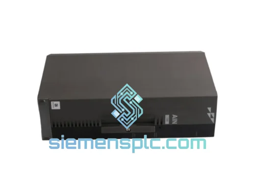
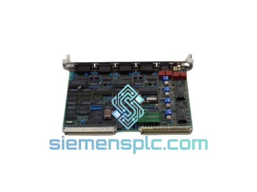
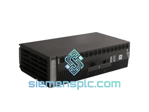
ABB P-HB-DOT-12010000 Safety Digital Output Module – AC500-S
AC500
Origin SE
Safety Digital Output Module
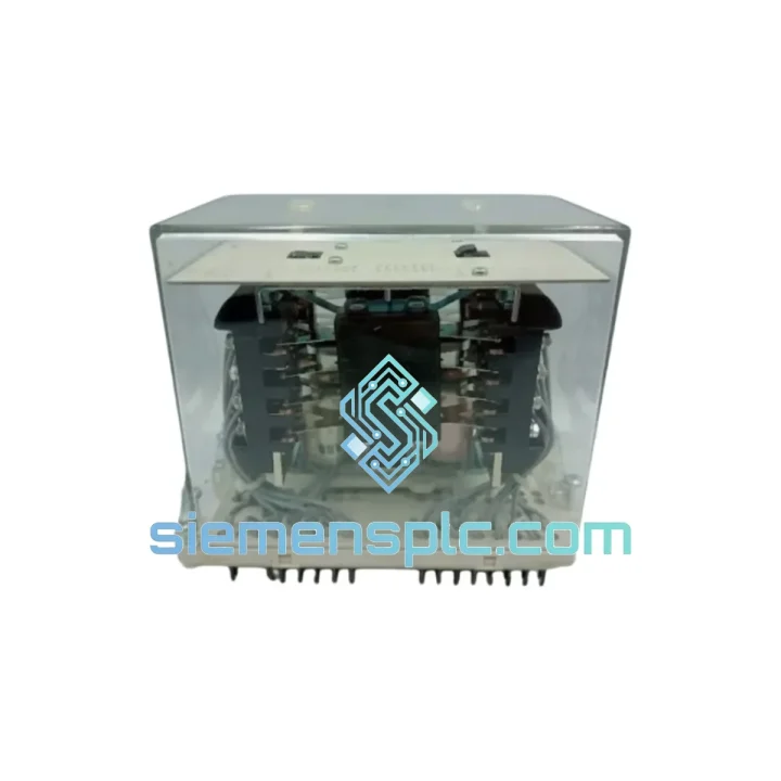
Request verified availability, condition, replacement risk review, packing options and courier lead time for RK251402-AP.
Click Request Quote and the part number is inserted into the inquiry form automatically.
Core fields for model confirmation and RFQ routing. Detailed product narrative remains below.
In any PLC-based control loop, the digital output stage is the terminal point where programmed logic translates into physical actuation. A relay output module must satisfy two competing demands simultaneously: it must provide complete galvanic isolation between the controller backplane and the field circuit, and it must sustain reliable contact switching across the full rated electrical and thermal envelope of the installation. The ABB RK251402-AP is a dedicated relay output module engineered for the AC500 S500 distributed I/O system, addressing both requirements through a hardware architecture that prioritizes contact integrity, channel-level isolation, and deterministic signal propagation.
The AC500 platform operates on a high-speed S500 I/O bus that supports synchronous data exchange between the CPU and expansion modules at cycle times as low as 1 ms. Within this architecture, the RK251402-AP functions as a field-side interface layer. Each relay channel presents a potential-free contact to the field circuit, meaning the switching element carries no reference to the PLC supply rail. This design eliminates ground loop currents that would otherwise introduce common-mode noise into analog measurement circuits sharing the same panel. The module mounts directly onto an S500 terminal unit — TA5211 or TA5212 depending on wiring configuration — using a tool-free snap-on mechanism that aligns the backplane connector without mechanical stress on the PCB edge fingers.
The relay contact mechanism itself is a bifurcated crossbar design, which maintains two independent contact points per pole. This geometry reduces the probability of contact weld under inductive load switching by distributing the arc energy across a larger contact surface area. For loads with high inrush characteristics — motor starters, solenoid valves, transformer primaries — the bifurcated contact geometry provides measurably longer mechanical service life compared to single-point contact designs. ABB rates the RK251402-AP contacts for a minimum of 10 million mechanical operations under no-load conditions and specifies electrical endurance curves at rated resistive and inductive loads in the module datasheet.
Thermal management within the module enclosure is passive, relying on the convective airflow path established by the DIN rail mounting orientation and the ventilation slots in the housing. The operating temperature range of −25 °C to +60 °C without derating reflects the thermal dissipation capacity of the relay coil driver circuit and the contact assembly. At the upper boundary, the coil driver maintains stable pull-in voltage across the specified supply tolerance band, preventing relay chatter under marginal supply conditions in high-ambient enclosures.
EMC performance is addressed at the hardware level through suppression networks on the relay coil driver outputs. When the CPU de-energizes a relay channel, the collapsing magnetic field in the coil generates a back-EMF transient. Without suppression, this transient couples into adjacent signal wiring through capacitive and inductive paths. The RK251402-AP incorporates transient suppression components that clamp the back-EMF spike within IEC 61000-4-4 burst immunity limits, protecting adjacent analog input channels from measurement errors caused by switching transients on the same terminal unit.
The module integrates diagnostic feedback to the AC500 CPU via the S500 bus. Channel-level status bits report relay coil energization state, allowing the application program to implement output verification logic — comparing commanded state against reported state to detect open-circuit coil faults or welded contacts. This diagnostic transparency is essential in safety-instrumented systems where output verification is a required function of the safety integrity level assessment.
Real-time Stock & RFQ: [email protected] | WhatsApp: +86 18359268345
| Parameter | Value |
|---|---|
| Part Number / SKU | RK251402-AP |
| Manufacturer | ABB |
| Product Series | AC500 S500 I/O System |
| Module Function | Digital Output – Relay Contact |
| Output Contact Type | Potential-free (volt-free) relay contact |
| Contact Configuration | Bifurcated crossbar, NO/NC per channel |
| Rated Switching Voltage (AC) | Up to 250 V AC |
| Rated Switching Voltage (DC) | Up to 30 V DC |
| Rated Switching Current | Per ABB datasheet (contact us for latest revision) |
| Galvanic Isolation | Channel-to-backplane; channel-to-channel |
| Mechanical Life | ≥ 10 million operations (no load) |
| Compatible Bus | AC500 S500 I/O bus |
| Compatible Terminal Units | TA5211, TA5212 |
| Mounting Method | DIN rail, tool-free snap-on to terminal unit |
| Operating Temperature | −25 °C to +60 °C |
| Storage Temperature | −40 °C to +70 °C |
| Protection Class | IP20 |
| Standards Compliance | IEC 61131-2, IEC 61000-4-4, CE, UL |
| Country of Origin | Germany |
| Warranty | 12 months against manufacturing defects |
The RK251402-AP’s hardware design reflects three principal engineering priorities: isolation integrity, switching reliability, and bus-synchronous diagnostics.
Isolation Architecture: The module implements two-stage isolation. The first stage separates the S500 bus logic supply from the relay coil driver circuit using an optocoupler barrier rated to withstand transient voltages consistent with IEC 61000-4-5 surge immunity requirements. The second stage is the relay contact itself, which provides galvanic separation between the coil circuit and the switched field load. This two-stage topology means that even a field-side fault — such as an insulation breakdown on a motor cable — cannot propagate a destructive voltage back through the optocoupler to the CPU backplane.
Coil Driver Circuit: The relay coil driver is implemented with a low-side switch topology, where the coil return path is controlled by a transistor referenced to the module’s internal logic ground. This configuration allows the driver to be protected by a current-limiting circuit that prevents coil burnout under sustained over-voltage conditions on the module supply rail. The driver also incorporates a flyback diode in parallel with the coil to provide a low-impedance path for the inductive kickback current during de-energization, supplemented by the external transient suppression network described above.
EMC Design: The PCB layout routes the relay coil drive signals on inner copper layers, shielded by ground planes on the outer layers. This stackup reduces radiated emissions from the switching transients on the coil drive lines. The terminal unit connector interface uses a controlled-impedance backplane trace to maintain signal integrity on the S500 bus at the rated communication frequency, preventing reflections that would corrupt the cyclic data exchange between the CPU and the I/O module.
Diagnostic Feedback Path: A contact monitoring circuit samples the relay contact state independently of the coil energization command. The sampled state is encoded into the module’s input data word and transmitted to the CPU on each S500 bus cycle. This allows the application program to implement output verification within the same PLC scan cycle in which the output command was issued, achieving a diagnostic coverage depth consistent with SIL 2 output verification requirements when combined with appropriate application-layer logic.
Every ABB RK251402-AP unit supplied through siemensplc.com is sourced from verified industrial distribution channels with full traceability to ABB’s manufacturing batch records. Units are inspected prior to dispatch for label integrity, connector pin condition, housing seal, and original ABB packaging authenticity markers. Anti-static packaging with moisture barrier film is applied for all international shipments to protect the module’s PCB and relay contact surfaces during air and sea freight transit.
Shipments originate from our warehouse in Xiamen, China — a major export hub with direct access to international air freight services and sea freight consolidation to all major global ports. Standard export documentation — commercial invoice, packing list, certificate of origin, and customs declaration — is prepared for every order. Incoterm options include EXW, FOB Xiamen, CIF, and DDP depending on the buyer’s logistics preference. For urgent replacement requirements, air freight dispatch within 24 hours of order confirmation is available to most destinations.
A 12-month warranty against manufacturing defects is provided on all genuine ABB modules. Warranty claims are processed with batch number verification against ABB’s production records. Technical pre-sales support — including compatibility verification against your AC500 CPU firmware revision and terminal unit part number — is available from our engineering team at no charge.
Email: [email protected]
WhatsApp: +86 18359268345
Web: siemensplc.com
Location: Xiamen, China
© 2026 siemensplc.com. All rights reserved.
We check the full part number, brand, series and visible nameplate information before quotation.
Sales confirms stock path, condition option, quantity and realistic lead time for export dispatch.
DHL, FedEx, UPS or buyer courier arrangements can be reviewed with packing requirements.
Similar brand or category products for fast comparison and multi-item RFQ lists.