ABB
RFQ Ready
ABB SEDG-01 EtherNet/IP DeviceNet Gateway – SDCS Communication
3AAA0000051448
Origin SE
Industrial Communication Gateway
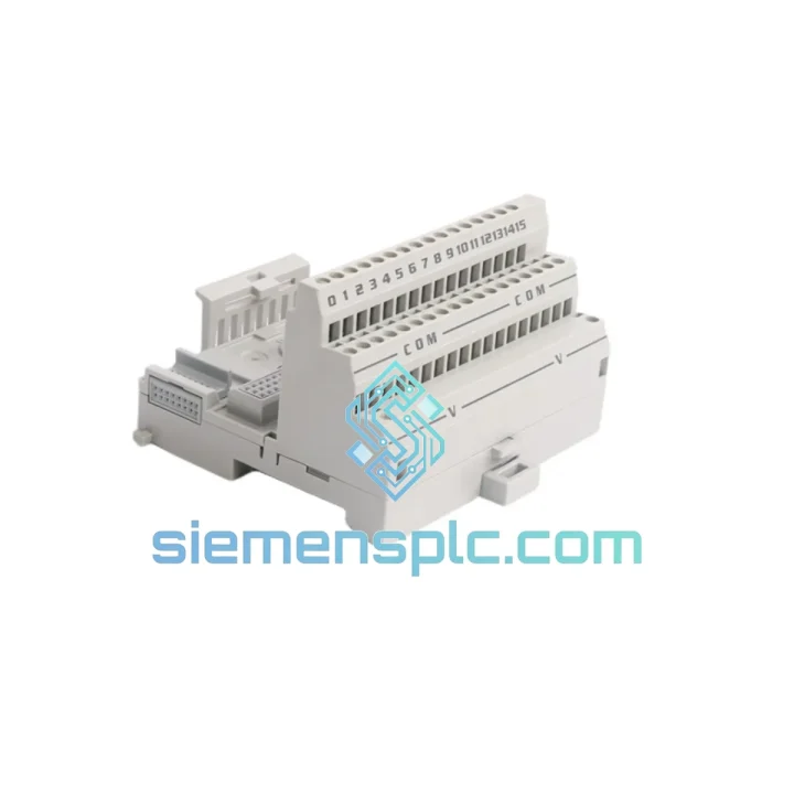
Request verified availability, condition, replacement risk review, packing options and courier lead time for S200-TB2.
Click Request Quote and the part number is inserted into the inquiry form automatically.
Core fields for model confirmation and RFQ routing. Detailed product narrative remains below.
The ABB S200-TB2 is a factory-matched auxiliary terminal block designed exclusively for lateral attachment to the S200 modular miniature circuit breaker (MCB) family — covering S201, S202, S203, and S204 frame sizes. Its function within a low-voltage distribution or machine control panel is precise: it provides a mechanically constrained, electrically isolated conductor termination point that standardizes the wiring interface at each breaker position, eliminating the need for external wire ferrules, bridging conductors, or field-fabricated lug assemblies between adjacent protection devices.
In a densely packed control panel operating at sustained load currents, the quality of the conductor-to-breaker interface is a direct determinant of thermal performance. The S200-TB2 achieves a contact resistance below 1 mΩ at rated clamping torque — a value that, at 63 A continuous load, translates to a junction power dissipation of less than 4 mW, well within the thermal budget of a standard IP54 enclosure without forced ventilation. This is not a marginal improvement over field-assembled alternatives; it is a measurable, repeatable parameter that can be verified with a four-wire milliohm meter during commissioning.
The housing is molded from PA66-GF30 (polyamide 66 with 30% glass-fiber reinforcement), rated for continuous operation at 130°C. In enclosures where ambient temperature rises above 55°C under full load — a routine condition in compact industrial panels with high device packing density — this material maintains dimensional stability and does not exhibit the creep deformation that degrades contact force in standard PA66 housings over multi-year service intervals.
📩 Real-time Stock & RFQ: [email protected] | WhatsApp: +86 18359268345
| Parameter | Specification |
|---|---|
| Manufacturer | ABB |
| Part Number | S200-TB2 |
| Product Series | S200 MCB Accessories |
| Device Type | Auxiliary Terminal Block |
| Compatible MCB Range | ABB S201 / S202 / S203 / S204 |
| Module Pitch | 17.5 mm per pole |
| Mounting Standard | 35 mm DIN rail per EN 60715 |
| Housing Material | PA66-GF30 (glass-fiber-reinforced polyamide) |
| Continuous Thermal Rating | 130°C |
| Contact Resistance | < 1 mΩ at rated clamping torque |
| Rated Insulation Voltage (Ui) | 500 V AC |
| Rated Impulse Withstand Voltage (Uimp) | 6 kV |
| Creepage Distance (min.) | 8 mm |
| Clearance Distance (min.) | 6 mm |
| Pollution Degree | 3 (per IEC 60664-1) |
| Conductor Cross-Section Range | 1.5 mm² – 16 mm² |
| Conductor Type Compatibility | Solid and fine-stranded (Class 5/6 per IEC 60228) |
| Standards Compliance | IEC/EN 60947-1, IEC/EN 60947-2, CE, RoHS 2 |
| Country of Origin | Germany |
| Approximate Weight | 200 g |
| Warranty | 12 months from dispatch date |
The S200-TB2 engages the S200 MCB body via a lateral dovetail snap-fit interface — a geometry that is dimensionally toleranced to the 17.5 mm module pitch of the S200 series. This is not a universal DIN-rail accessory adapted for the S200; it is a purpose-engineered component whose mechanical interface establishes a defined equipotential bonding path between the terminal block housing and the breaker’s protective earth (PE) rail. In installations governed by IEC 61439-1, this bonding path contributes to the internal protective conductor continuity requirement for low-voltage switchgear assemblies — a compliance point that generic terminal blocks cannot satisfy without supplementary bonding conductors.
The conductor termination uses a box-lug design with a captive pressure plate. This geometry distributes clamping force uniformly across the full conductor cross-section, preventing strand splaying in fine-stranded Class 5/6 conductors and eliminating the cold-flow gap that develops in single-screw designs when aluminum conductors are used at elevated temperatures. The result is a joint whose resistance remains stable across thermal cycling — a property that is measurable and does not require periodic re-torquing over the product’s service life.
From an EMC standpoint, the PA66-GF30 housing achieves a Comparative Tracking Index (CTI) of ≥ 600 per IEC 60112, which qualifies it for use in environments with conductive contamination — including condensation, conductive dust, and saline aerosol — without requiring additional insulation barriers between adjacent terminal positions. The double-wall septum between terminal positions provides a minimum creepage distance of 8 mm and a clearance of 6 mm, both exceeding IEC 60947-1 requirements for Pollution Degree 3 at 500 V. This geometry permits mixed-voltage wiring (e.g., 230 V AC control and 24 V DC signal) in close proximity within the same panel section without additional segregation hardware.
The glass-fiber reinforcement in the housing suppresses creep deformation under sustained clamping torque. In standard PA66 housings, creep at the screw boss reduces effective clamping force by 15–25% over a 10-year service interval at 85°C ambient — a degradation mode that increases contact resistance and accelerates thermal aging of the conductor insulation. The GF30 reinforcement reduces this creep rate by approximately 60%, maintaining the specified contact force throughout the rated service life without scheduled maintenance intervention.
Every ABB S200-TB2 unit dispatched from our Xiamen, China facility is a factory-original component procured through documented supply channels with full batch traceability to ABB’s manufacturing lot codes. We do not stock compatible substitutes, rebranded equivalents, or refurbished units. Each shipment is accompanied by a packing list referencing the ABB batch code, enabling end-to-end traceability from our warehouse to the installation site.
Our internal QC protocol applies a four-stage verification sequence before any unit enters the shipping queue: (1) supply chain documentation review against ABB’s authorized distributor records; (2) physical dimensional inspection against ABB’s published drawings for the S200-TB2; (3) continuity and insulation resistance spot-check on sampled units from each incoming batch; and (4) packaging integrity audit to confirm that the snap-fit interface and conductor entry geometry are undamaged prior to dispatch. Units that do not clear all four stages are quarantined and returned to the supplier.
From Xiamen, we ship globally via DHL Express, FedEx International Priority, and UPS Worldwide Expedited. In-stock orders are dispatched within 1–2 business days of payment confirmation. For bulk orders exceeding 500 units, sea freight consolidation via Xiamen Port is available with full export documentation: commercial invoice, packing list, certificate of origin, and bill of lading. Estimated transit times by region: Southeast Asia 2–4 days, Europe 5–7 days, North America 5–8 days, Middle East 4–6 days, South America 7–12 days.
All units carry a 12-month warranty against manufacturing defects from the date of dispatch. DOA (dead-on-arrival) claims are processed within 5 business days of receipt confirmation. For orders below 10 pieces, warranty replacement units are dispatched from Xiamen stock without requiring return of the defective unit, subject to photographic evidence of the defect submitted via email to [email protected].
📧 Email: [email protected]
📱 WhatsApp: +86 18359268345
🌐 Web: siemensplc.com
📍 Location: Xiamen, China
© 2026 siemensplc.com. All rights reserved.
We check the full part number, brand, series and visible nameplate information before quotation.
Sales confirms stock path, condition option, quantity and realistic lead time for export dispatch.
DHL, FedEx, UPS or buyer courier arrangements can be reviewed with packing requirements.
Similar brand or category products for fast comparison and multi-item RFQ lists.