ABB
RFQ Ready
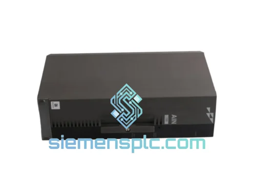
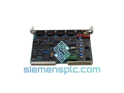
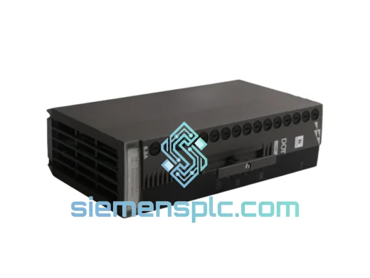
ABB P-HB-DOT-12010000 Safety Digital Output Module – AC500-S
AC500
Origin SE
Safety Digital Output Module
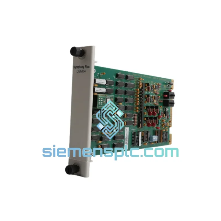
Request verified availability, condition, replacement risk review, packing options and courier lead time for SPDSM04.
Click Request Quote and the part number is inserted into the inquiry form automatically.
Core fields for model confirmation and RFQ routing. Detailed product narrative remains below.
Within a programmable automation controller architecture, the accuracy of process feedback is bounded by the weakest link in the signal acquisition chain. For applications where the primary process variable is expressed as a pulse train — turbine flow meters generating K-factor pulses, incremental encoders tracking shaft position, proximity sensors monitoring conveyor throughput, or S0-interface energy sub-meters — the signal conditioning module between the field device and the CPU’s process image determines whether the control loop operates on accurate data or on a software-approximated estimate subject to scan-cycle aliasing.
The ABB SPDSM04 addresses this constraint by implementing four fully independent hardware counter channels, each capable of sustained acquisition at input frequencies up to 100 kHz. The counter logic operates asynchronously from the AC500 CPU’s task scheduler: pulses are captured, accumulated, and held in a 32-bit register that is read by the CPU at each S-Bus scan boundary. This decoupling means that a CPU executing a 20 ms scan cycle — typical for a mid-complexity AC500 application with active Modbus TCP and PROFIBUS DP communication stacks — will still receive a complete, loss-free pulse count for a 100 kHz input signal. At that frequency, 2,000 pulses arrive during a single 20 ms scan interval; every one is counted.
The module supports four distinct measurement modes, selectable per channel without hardware modification: cumulative pulse totalization for batch and custody-transfer accounting; frequency measurement using a configurable gate-time window for flow rate computation; period measurement computing the interval between consecutive rising edges for low-speed, high-resolution tachometry; and direct RPM output derived from period measurement with a user-configured pulses-per-revolution divisor. In a water treatment plant, for example, a single SPDSM04 can simultaneously totalize influent volume on channel 1, measure effluent pump speed on channel 2, monitor a chemical dosing meter on channel 3, and track a UV-reactor flow switch on channel 4 — four distinct measurement functions from one rack slot.
The 32-bit counter depth per channel accommodates 4,294,967,295 counts before rollover. At a typical turbine meter K-factor of 1,000 pulses per liter, this represents 4.29 million liters of accumulated volume before a software overflow-handling routine is required — sufficient for most batch cycle durations without counter management overhead in the application program.
Real-time Stock & RFQ: [email protected] | WhatsApp: +86 18359268345
| Parameter | Specification |
|---|---|
| Part Number | SPDSM04 |
| Manufacturer | ABB Ltd. |
| Compatible Platform | ABB AC500 PAC (standard CPU rack, S500 I/O bus) |
| Module Function | 4-Channel Pulse / Frequency / Period / Speed Input |
| Number of Input Channels | 4 × independent hardware counter channels |
| Maximum Input Frequency | 100 kHz per channel (all channels simultaneous) |
| Counter Register Width | 32-bit per channel (0 to 4,294,967,295 counts) |
| Measurement Modes | Pulse totalization, Frequency (Hz), Period (µs), RPM |
| Supported Signal Standards | HTL (10–30 V DC), TTL (5 V DC), NPN open-collector, PNP sourcing, S0 (IEC 62053-31) |
| HTL Input Threshold — Low | ≤ 5 V DC |
| HTL Input Threshold — High | ≥ 15 V DC |
| TTL Input Threshold — Low | ≤ 0.8 V DC |
| TTL Input Threshold — High | ≥ 2.0 V DC |
| Input Current per Channel | ≤ 10 mA at 24 V DC nominal |
| Galvanic Isolation | Optocoupler per channel; field-to-logic isolation barrier |
| Isolation Voltage (rated) | 500 V DC (field to backplane logic) |
| Module Supply | 24 V DC via AC500 backplane; no external auxiliary supply |
| Power Dissipation | ≤ 2.5 W |
| Operating Temperature | −25 °C to +60 °C |
| Storage Temperature | −40 °C to +70 °C |
| Relative Humidity | 5–95 % RH, non-condensing (IEC 60068-2-78) |
| Vibration Resistance | IEC 60068-2-6: 5–150 Hz, 1 g |
| Shock Resistance | IEC 60068-2-27: 15 g, 11 ms |
| EMC Immunity | EN 61000-6-2 (Industrial); EFT/Burst Level 3, Surge Level 3 |
| EMC Emissions | EN 55011 Class A |
| Protection Class | IP20 |
| Dimensions (W × H × D) | 35 mm × 130 mm × 110 mm |
| Backplane Interface | AC500 S-Bus (internal, cycle-synchronous data transfer) |
| Configuration Environment | ABB Automation Builder (IEC 61131-3) |
| Certifications | CE (EMC Directive 2014/30/EU, LVD 2014/35/EU), UL 508, cUL, RoHS |
| Country of Origin | Germany |
| Warranty | 12 months from shipment date |
Optocoupler Isolation and High-Speed Signal Fidelity: Each input channel routes through a dedicated high-speed optocoupler before reaching the counter logic. Standard optocouplers used in general-purpose digital I/O modules have current-transfer-ratio (CTR) characteristics that limit usable bandwidth to 10–20 kHz — adequate for discrete on/off sensing but insufficient for pulse acquisition above that threshold. The SPDSM04 employs optocouplers selected for high-speed operation, with propagation delay characteristics that preserve pulse edge timing at 100 kHz input rates. The isolation barrier provides a 500 V DC rated separation between field wiring and the 3.3 V counter logic domain, blocking ground-loop currents and common-mode transients generated by variable-frequency drives, contactors, and inductive load switching in the same panel or cable tray.
Asynchronous Counter Architecture and S-Bus Latching: The counter registers operate on a clock domain independent of the AC500 CPU’s task execution cycle. Pulse edges are captured and accumulated in real time by dedicated counter silicon — whether implemented as discrete counter ICs or as FPGA fabric, the functional result is identical: no pulse is gated by CPU availability. At the S-Bus scan boundary, the counter register value is atomically latched into a transfer buffer and presented to the CPU process image. The CPU reads a stable 32-bit value that reflects the total accumulated count up to that precise moment, with no possibility of reading a partially-written value mid-update. This atomic latch mechanism is the hardware guarantee that eliminates the race conditions inherent in software-polled counter implementations on shared data buses.
Period Measurement Mode for Low-Speed Tachometry: Frequency-gate-time measurement has a fundamental resolution limitation at low speeds: a 100 ms gate window can only resolve frequency to ±10 Hz, which at a 60-pulse-per-revolution encoder corresponds to ±10 RPM. For applications requiring sub-1 RPM resolution — slow-speed conveyor monitoring, large-diameter pump shaft tachometry, or mill rotation sensing — the period measurement mode measures the time between consecutive rising edges using the module’s internal high-resolution timebase. At 1 RPM with a 60-pulse encoder, the inter-pulse period is 1 second; the module measures this with microsecond-level resolution, yielding a speed measurement accurate to better than 0.001 RPM. This capability is not achievable through software interrupt timing on a CPU with a multi-millisecond scan cycle.
S0 Interface Native Support: The IEC 62053-31 S0 interface is a passive current-sink standard used by electricity, gas, water, and heat meters for pulse output. S0 signals require a pull-up voltage source (typically 12–27 V DC) and a defined sink current (5–27 mA) at the receiving end. The SPDSM04 input stage provides this pull-up internally, eliminating the external signal conditioning components — relay modules, optocoupler boards, or resistor networks — that would otherwise be required to interface S0 meters to a standard digital input module. In energy sub-metering applications with multiple meter points, this native compatibility reduces panel wiring complexity and eliminates a category of potential failure points.
PCB EMC Architecture: The module’s printed circuit board partitions the analog input front-end (optocoupler stage, pull-up networks, input filtering) from the digital counter logic using a split ground plane topology. Ferrite beads on the backplane power supply rails attenuate high-frequency switching noise conducted from other modules in the rack. Input signal traces are routed with controlled impedance and shielded from adjacent high-frequency digital traces. These design measures collectively support the module’s EN 61000-6-2 immunity rating, including 2 kV EFT/burst (IEC 61000-4-4 Level 3) and 1 kV surge (IEC 61000-4-5 Level 3) — the standard test levels for industrial control equipment in environments with significant conducted interference sources.
Units shipped from siemensplc.com’s Xiamen, China operations are sourced through traceable supply channels with batch-level documentation linking each unit to ABB’s authorized distribution network. The incoming inspection sequence applied to each SPDSM04 covers: physical examination of PCB, connector, and label integrity against ABB factory standards; firmware version confirmation against the current ABB AC500 release matrix; functional bench test on an AC500 rack verifying counter operation, S-Bus communication, and diagnostic flag behavior across all four channels; and ESD-safe packaging with anti-static bag, conductive foam insert, desiccant sachet, and humidity indicator card.
Export shipments depart Xiamen via DHL Express, FedEx International Priority, or UPS Worldwide Expedited. Transit times to Western Europe average 3–5 business days; to North America, 4–6 business days; to the Middle East and Southeast Asia, 2–4 business days. Each shipment is accompanied by a commercial invoice, packing list, certificate of origin, and HS code declaration (HS 8537.10). For projects requiring UL or CE conformity documentation, certified declaration copies are included in the shipment package at no additional charge. The 12-month warranty from shipment date covers manufacturing defects and functional failures under normal operating conditions. Dead-on-arrival replacements are processed within 5 business days of confirmed fault verification.
Email: [email protected]
WhatsApp: +86 18359268345
Web: siemensplc.com
Location: Xiamen, China
© 2026 siemensplc.com. All rights reserved.
We check the full part number, brand, series and visible nameplate information before quotation.
Sales confirms stock path, condition option, quantity and realistic lead time for export dispatch.
DHL, FedEx, UPS or buyer courier arrangements can be reviewed with packing requirements.
Similar brand or category products for fast comparison and multi-item RFQ lists.