ABB
RFQ Ready
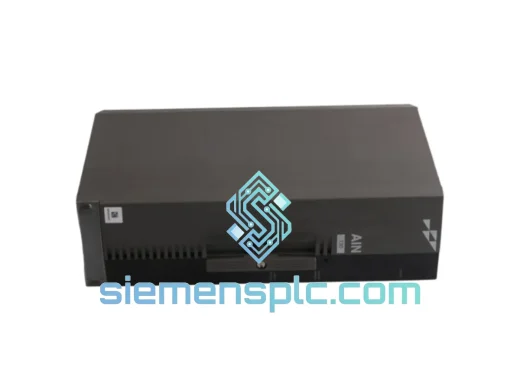
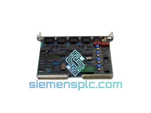
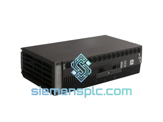
ABB P-HB-DOT-12010000 Safety Digital Output Module – AC500-S
AC500
Origin SE
Safety Digital Output Module
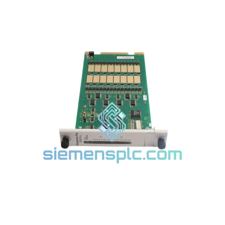
Request verified availability, condition, replacement risk review, packing options and courier lead time for SPDSO14.
Click Request Quote and the part number is inserted into the inquiry form automatically.
Core fields for model confirmation and RFQ routing. Detailed product narrative remains below.
The ABB SPDSO14 is a 14-channel transistor-based digital output slave module engineered for deployment within the ABB AC500 programmable logic controller platform. Its primary function within a control loop is to translate CPU-issued logical commands into discrete 24 V DC switching signals that drive field actuators — solenoid valves, motor contactors, indicator lamps, and relay coils — with deterministic timing governed by the AC500 S-Bus cycle. Unlike relay-output modules, the SPDSO14 employs solid-state transistor switching, which eliminates mechanical wear, reduces switching latency to sub-millisecond levels, and supports output frequencies unsuitable for electromechanical contacts.
In distributed I/O topologies, the SPDSO14 operates as a slave node on the AC500 internal S-Bus, receiving process image data from the CPU module across the backplane at each scan cycle. The module’s output register is updated synchronously with the CPU’s output process image, ensuring that field-side switching events are temporally aligned with the control program’s execution state. This synchronous update mechanism is critical in applications where output sequencing — such as valve interlock logic or conveyor step control — must be free of inter-cycle jitter.
Real-time Stock & RFQ: [email protected] | WhatsApp: +86 18359268345
| Parameter | Specification |
|---|---|
| Part Number | SPDSO14 |
| Manufacturer | ABB |
| Module Series | AC500 S500 I/O |
| Module Function | Digital Output Slave |
| Number of Output Channels | 14 |
| Output Technology | Transistor (solid-state), sourcing type |
| Rated Output Voltage | 24 V DC |
| Maximum Output Current per Channel | 0.5 A (consult datasheet for derating) |
| Total Module Load Current | ≤ 4 A aggregate |
| Communication Interface | AC500 S-Bus (internal backplane); PROFIBUS-DP via coupler |
| Mounting Method | DIN rail via AC500 terminal unit (e.g., TA526) |
| Protection Class | IP20 |
| Operating Temperature | 0 °C to +60 °C |
| Storage Temperature | −25 °C to +70 °C |
| Relative Humidity | 5 % to 95 %, non-condensing |
| Supply Voltage (Logic) | 24 V DC via AC500 system bus |
| Short-Circuit Protection | Electronic, per channel |
| Diagnostic Functions | Wire-break detection, overload indication |
| Certifications | CE, UL (verify current listing with ABB) |
| Approximate Weight | 200 g |
| Warranty | 12 months from date of shipment |
The SPDSO14’s output stage is built around a bank of N-channel MOSFETs arranged in a sourcing configuration. Each channel’s gate drive circuit is isolated from the S-Bus logic domain by an optocoupler barrier rated for a minimum of 500 V AC isolation voltage. This galvanic separation between the field-side 24 V DC load circuit and the 3.3 V logic domain of the S-Bus interface prevents ground-loop currents — a common source of spurious switching in industrial environments with long cable runs — from corrupting the module’s internal state registers.
EMC performance is addressed at the PCB layout level. The module’s power and signal planes are separated by a ground pour that acts as a Faraday shield, attenuating capacitively coupled high-frequency noise from adjacent switching power supplies or variable-frequency drives. Transient suppression diodes (TVS) are placed at each output terminal to clamp inductive kickback from solenoid coils to within the MOSFET’s avalanche rating, eliminating the need for external flyback diodes in most standard actuator wiring configurations.
The S-Bus interface logic implements a watchdog timer that monitors communication frame integrity. If the CPU fails to refresh the output process image within the configured watchdog timeout — due to CPU fault, cable disconnection, or bus overload — the module autonomously drives all 14 outputs to a defined safe state (de-energized by default, configurable to hold-last-value in Automation Builder). This fail-safe behavior is implemented in hardware logic, independent of the module’s firmware, ensuring it operates even during firmware update cycles.
Channel-level diagnostic circuitry continuously monitors load current against a programmable threshold. An open-load condition (wire break or disconnected actuator) is detected when the measured current falls below the minimum load threshold during an active output state. Overload conditions trigger electronic current limiting before thermal shutdown, with the fault status written to the module’s diagnostic register and propagated to the CPU’s diagnostic buffer within one S-Bus cycle — typically under 1 ms in standard AC500 configurations.
Every ABB SPDSO14 unit supplied by siemensplc.com is sourced through verified distribution channels with full traceability documentation. Pre-shipment inspection covers visual integrity assessment, label and serial number verification against ABB production records, and functional power-on testing where test fixtures are available. Anti-counterfeit protocols include holographic label authentication and cross-referencing of date codes against known ABB manufacturing batches.
All units are dispatched from our Xiamen, China warehouse in ESD-safe packaging with desiccant inserts to protect against humidity ingress during transit. Xiamen’s port infrastructure supports direct air freight connections to major industrial hubs across Europe, Southeast Asia, the Middle East, and the Americas. Standard air freight transit times are 3–7 business days to most destinations. Express DHL/FedEx options are available for urgent requirements, with door-to-door delivery achievable within 2–3 business days to most regions. All shipments include commercial invoice, packing list, and certificate of origin documentation to facilitate customs clearance. A 12-month warranty covers manufacturing defects and functional failure under normal operating conditions.
Email: [email protected]
WhatsApp: +86 18359268345
Web: siemensplc.com
Location: Xiamen, China
© 2026 siemensplc.com. All rights reserved.
We check the full part number, brand, series and visible nameplate information before quotation.
Sales confirms stock path, condition option, quantity and realistic lead time for export dispatch.
DHL, FedEx, UPS or buyer courier arrangements can be reviewed with packing requirements.
Similar brand or category products for fast comparison and multi-item RFQ lists.