ABB
RFQ Ready
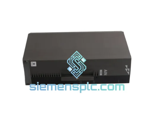
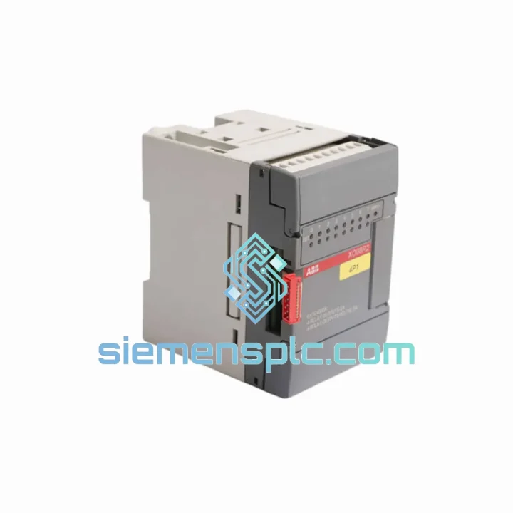
ABB P-HB-DOT-12010000 Safety Digital Output Module – AC500-S
AC500
Origin SE
Safety Digital Output Module
Request verified availability, condition, replacement risk review, packing options and courier lead time for XO08R2-A4.
Click Request Quote and the part number is inserted into the inquiry form automatically.
Core fields for model confirmation and RFQ routing. Detailed product narrative remains below.
The XO08R2-A4.0 occupies a well-defined position in the ABB AC500 control hierarchy: it is the terminal switching authority between the CPU’s deterministic output scan and the physical field devices that execute process commands. In a relay output stage, the module does not merely pass a logic signal — it commits a mechanical contact closure that carries real load current, isolates the PLC backplane from inductive transients, and provides the galvanic separation that protects the entire controller from field-side fault propagation. Understanding this role is essential for any system architect selecting output modules for process-critical applications.
Catalog number 1SBP260109R1001 identifies this module within ABB’s AC500 I/O extension family. The AC500 platform uses a terminal unit architecture: the XO08R2-A4.0 plugs into a compatible TU-series terminal unit, which provides the field wiring terminals and backplane bus connection. This separation of electronics from field wiring is a deliberate design choice — it allows module replacement without disturbing field cable terminations, reducing mean time to repair (MTTR) in live panel environments.
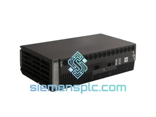
The module provides eight independent relay output channels. Each channel operates as a dry contact (potential-free), meaning the switching element carries no inherent voltage — the load circuit supplies its own power. This architecture permits mixed-voltage field wiring on a single module: one channel may switch 24 V DC to a solenoid valve while an adjacent channel switches 230 V AC to a motor contactor coil, without any cross-interference at the module level. The relay contacts are rated for both resistive and inductive loads, with the inductive load rating accounting for the back-EMF suppression requirements of coil-type actuators.
Within the AC500 backplane communication model, the XO08R2-A4.0 exchanges output data with the CPU via the S500 I/O bus. The CPU writes the output image table during each scan cycle; the I/O bus transfers this image to the extension module, which latches the relay coil states accordingly. The latching behavior ensures that relay states are held stable between scan cycles — a critical property for output modules driving contactors, where chattering contacts would cause mechanical wear and process instability. The bus cycle time is deterministic and bounded, which means the worst-case output update latency is calculable and can be factored into safety timing analyses.
From an EMC standpoint, the relay contact isolation provides inherent common-mode noise rejection between the PLC logic domain and the field power domain. The module’s housing and PCB layout conform to ABB’s AC500 EMC design rules, which include controlled impedance traces on the bus interface, decoupling capacitors at the backplane connector, and a grounded metal shield between the relay coil drive circuitry and the bus interface logic. These measures allow the module to operate within IEC 61000-4 test levels for conducted and radiated immunity — a requirement for CE marking and deployment in industrial environments with variable-frequency drives, arc welding equipment, or high-current switching loads nearby.
The XO08R2-A4.0 is engineered for continuous duty in ambient temperatures from 0 °C to +60 °C, with storage ratings extending to -25 °C / +70 °C. The relay contacts are rated for a defined number of mechanical and electrical switching cycles, with the electrical endurance figure dependent on load type and current magnitude. For applications requiring high switching frequency or long service intervals without maintenance access, the relay endurance specification should be cross-referenced against the expected switching rate to confirm service life adequacy.
Real-time Stock & RFQ: [email protected] | WhatsApp: +86 18359268345
| Parameter | Value |
|---|---|
| Part Number (Catalog No.) | 1SBP260109R1001 |
| Model | XO08R2-A4.0 |
| Brand | ABB |
| Series | AC500 S500 I/O Extension |
| Output Type | Relay, dry contact (potential-free) |
| Number of Output Channels | 8 |
| Rated Load Voltage (AC) | Up to 250 V AC |
| Rated Load Voltage (DC) | Up to 30 V DC |
| Rated Current per Channel | 2 A (resistive load) |
| Contact Type | SPDT (Form C) per channel |
| Isolation | Galvanic, relay coil to contact |
| Bus Interface | ABB S500 I/O extension bus |
| Mounting | Via AC500 TU-series terminal unit, 35 mm DIN rail |
| Operating Temperature | 0 °C to +60 °C |
| Storage Temperature | -25 °C to +70 °C |
| Weight | 260 g |
| EMC Compliance | IEC 61000-4 series, CE marked |
| Degree of Protection | IP20 (module body) |
| Warranty | 12 months from date of shipment |
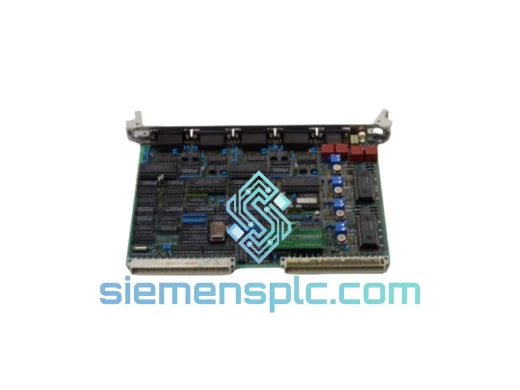
The relay output stage in the XO08R2-A4.0 is implemented with individual relay coil drivers per channel, each driven by an optocoupler-isolated transistor stage. This two-stage isolation chain — optocoupler between bus logic and coil driver, relay contact between coil driver and field load — creates a double-barrier isolation architecture. The first barrier (optocoupler) prevents bus-side logic ground from coupling to the coil drive supply; the second barrier (relay contact) prevents field-side voltage from reaching the coil drive circuitry. The result is that a field-side short circuit or overvoltage event cannot propagate backward through the module to corrupt the S500 bus or the CPU backplane.
The relay coil drive circuit incorporates a freewheeling diode across each coil. When the coil is de-energized, the collapsing magnetic field generates a back-EMF spike; the freewheeling diode clamps this spike to approximately 0.7 V above the coil supply rail, preventing the transistor driver from entering avalanche breakdown. This protection is internal to the module and does not require external suppression components on the field wiring side for DC coil loads. For AC coil loads, the relay contact itself is the switching element, and the coil drive circuit is not in the field current path.
The S500 bus interface on the XO08R2-A4.0 uses a synchronous serial protocol with CRC error detection. Each bus frame includes a status byte that the module returns to the CPU, confirming receipt of the output command. If the module detects a bus communication error (CRC mismatch, frame timeout), it holds the last valid relay states rather than defaulting to all-off — a deliberate fail-hold behavior that prevents unintended process interruptions from transient bus noise. This behavior is configurable in the CPU’s I/O configuration parameters for applications where fail-safe-off is required instead.
The PCB layout within the module separates the bus interface section from the relay coil drive section using a ground plane split, with the two sections connected only at a single star-ground point. This layout technique minimizes the common-impedance coupling between the high-frequency bus signals and the relay switching transients, which can generate broadband noise in the 1–100 MHz range. The relay coil drive traces are routed away from the bus interface traces, and the relay bodies are positioned at the field-side edge of the PCB to minimize the distance between the relay contacts and the terminal unit’s field wiring connectors.
Every XO08R2-A4.0 unit supplied by siemensplc.com is sourced from verified supply chains carrying ABB factory origin documentation. Prior to shipment, each module undergoes part number verification against ABB’s official catalog database, physical inspection of housing integrity and connector condition, and authenticity screening to eliminate counterfeit risk. Units are packed in anti-static bags with moisture barrier packaging, suitable for air freight and sea freight transit conditions.
Shipments originate from Xiamen, China — a major export hub with direct access to international air cargo services via Xiamen Gaoqi International Airport and sea freight via Xiamen Port. Standard export documentation includes commercial invoice, packing list, and certificate of origin. Additional documentation such as material safety data sheets, CE declarations of conformity, or third-party inspection certificates can be arranged on request. DHL Express, FedEx International Priority, and consolidated sea freight options are available, with full shipment tracking provided from dispatch to delivery. Typical air freight transit times to Southeast Asia are 3–5 business days; to Europe and the Americas, 5–8 business days.
All units carry a 12-month warranty from the date of shipment, covering manufacturing defects and functional failures under normal operating conditions. Warranty claims are processed with replacement unit dispatch upon receipt and inspection of the returned module.
Email: [email protected]
WhatsApp: +86 18359268345
Web: siemensplc.com
Location: Xiamen, China
© 2026 siemensplc.com. All rights reserved.
We check the full part number, brand, series and visible nameplate information before quotation.
Sales confirms stock path, condition option, quantity and realistic lead time for export dispatch.
DHL, FedEx, UPS or buyer courier arrangements can be reviewed with packing requirements.
Similar brand or category products for fast comparison and multi-item RFQ lists.