Allen-Bradley
RFQ Ready
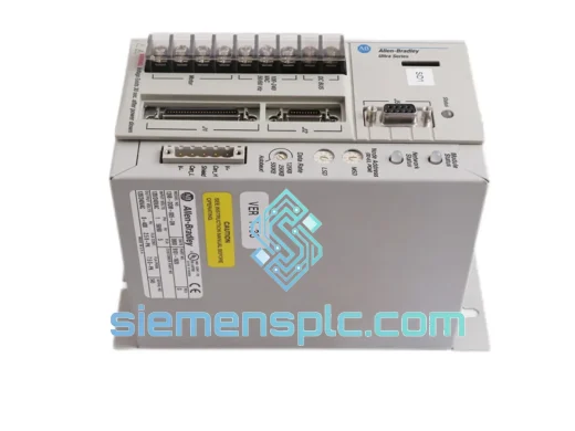
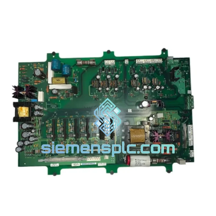
Allen-Bradley 1336-MOD-KB010 Dynamic Brake Module – 1336 PLUS Series
1336 PLUS
Origin US
Dynamic Brake Module
Request verified availability, condition, replacement risk review, packing options and courier lead time for 1336-BDB-SP17C.
Click Request Quote and the part number is inserted into the inquiry form automatically.
Core fields for model confirmation and RFQ routing. Detailed product narrative remains below.
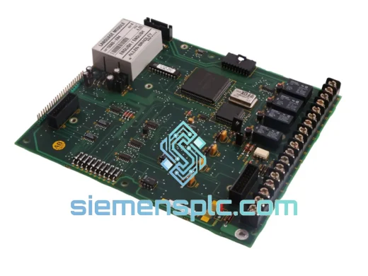
The Allen-Bradley 1336-BDB-SP17C (assembly reference 74101-482-51) is the base drive board assembly for the Rockwell Automation 1336 PLUS AC drive platform. Within the drive’s control architecture, this board occupies the central signal-processing layer: it interfaces directly with the gate-driver sub-board, receives velocity and torque reference signals from the main control board, and executes the PWM switching algorithm that governs IGBT firing sequences. Its removal or failure results in complete loss of drive output — making it a tier-1 critical spare for any facility running 1336 PLUS drives in continuous-process or high-availability applications.
Unlike generic replacement boards sourced from secondary markets, the 1336-BDB-SP17C carries Rockwell Automation’s internal revision traceability. The assembly number 74101-482-51 encodes the PCB revision level, component BOM version, and manufacturing lot — data that is essential when cross-referencing against drive firmware compatibility matrices. Substituting an incorrect revision can introduce timing mismatches in the PWM dead-band control, leading to nuisance overcurrent trips or, in worst cases, IGBT shoot-through events.
Real-time Stock & RFQ: [email protected] | WhatsApp: +86 18359268345
| Parameter | Specification |
|---|---|
| Manufacturer | Allen-Bradley / Rockwell Automation |
| Part Number | 1336-BDB-SP17C |
| Assembly / Reference No. | 74101-482-51 |
| Component Classification | Base Drive Board (PC Board Assembly) |
| Compatible Drive Family | 1336 PLUS AC Drive Series |
| Drive Voltage Class | 200–240 V AC / 380–480 V AC / 500–600 V AC (frame-dependent) |
| Control Bus Interface | Parallel backplane ribbon interface to main control board |
| Gate Drive Output | 6-channel isolated IGBT gate signals (3-phase bridge) |
| PWM Carrier Frequency Range | 2 kHz – 8 kHz (configurable via Parameter 54 in 1336 PLUS firmware) |
| Isolation Barrier | Opto-coupler isolation between logic-level control signals and gate drive stage |
| Operating Temperature | 0 °C to +50 °C (derating applies above 40 °C per Rockwell thermal guidelines) |
| Storage Temperature | –40 °C to +85 °C |
| Humidity | 5% – 95% RH, non-condensing |
| PCB Finish | HASL / ENIG (revision-dependent); conformal coating on production units |
| Approximate Board Dimensions | ~280 mm × 180 mm (verify against drive frame before ordering) |
| Weight | ~300 g |
| Country of Origin | USA (Rockwell Automation manufacturing) |
| Warranty | 12 months against manufacturing defects from date of shipment |
The 1336-BDB-SP17C operates at the boundary between the drive’s digital control domain and its high-voltage power stage. Understanding its internal logic is essential for accurate fault diagnosis and reliable replacement decisions.
PWM Signal Path and Dead-Band Management: The board receives six discrete PWM command signals from the main control board via an optically isolated parallel interface. Each signal passes through a dedicated opto-coupler stage — typically a high-speed HCPL-314J or equivalent — before entering the gate driver IC. The dead-band insertion logic (preventing simultaneous conduction of upper and lower IGBTs in the same phase leg) is implemented in hardware on this board, not in firmware. This means dead-band timing is deterministic and immune to software latency — a critical design choice for drives operating at higher PWM frequencies where shoot-through risk is elevated.
EMC Design and Noise Immunity: The board employs a multi-layer PCB stack with dedicated ground planes separating the low-voltage logic layer from the gate-drive power layer. Ferrite beads are placed on gate signal traces at the boundary between the opto-coupler output and the gate driver input to suppress high-frequency switching transients that could couple back into the control logic. The board’s ground reference is star-connected to the drive chassis at a single point, minimizing circulating ground currents that are a common source of nuisance fault trips in high-dV/dt environments.
Fault Detection and Desaturation Protection: Each gate driver channel incorporates a desaturation detection circuit. If an IGBT fails to fully saturate during a switching event — indicating an overcurrent condition or device degradation — the desaturation circuit pulls the gate low within 2–3 µs and asserts a fault signal back to the main control board. This hardware-level protection operates independently of the firmware fault-handling loop, providing a sub-microsecond response that firmware polling cannot match. The fault signal is latched until the drive is reset, preventing repeated fault-clear-retrigger cycles that could thermally stress a marginal IGBT.
Power Supply Distribution: The board derives its gate-drive bias voltages (+15 V / –8 V per phase leg) from isolated DC-DC converter modules mounted on the board itself. Each phase leg has an independent isolated supply, ensuring that a fault in one phase leg’s gate drive circuit does not collapse the supply rail for the remaining two phases — a design that improves fault containment and simplifies post-fault diagnosis.
Every unit of the Allen-Bradley 1336-BDB-SP17C 74101-482-51 supplied through siemensplc.com is sourced from verified channels — authorized distributors, OEM surplus with intact factory packaging, or certified refurbishers operating under documented quality management systems. We do not source from unverified secondary markets or brokers unable to provide supply chain documentation.
Inspection Protocol: Each board undergoes a four-stage inspection before dispatch: (1) label and date-code authentication against Rockwell Automation reference data; (2) visual inspection of PCB surfaces, solder joints, component population, and connector integrity; (3) ESD-safe handling verification throughout the inspection process; (4) secure packaging in anti-static bags with foam cushioning and moisture-barrier outer packaging for international transit.
Logistics from Xiamen, China: Our warehouse is located in Xiamen, Fujian Province — a major export hub with direct access to DHL Express, FedEx International Priority, UPS Worldwide Expedited, and TNT service networks. In-stock units are dispatched within 1–3 business days of order confirmation. For urgent requirements, same-day dispatch is available for orders confirmed before 14:00 CST. Transit times to major industrial regions: Southeast Asia 2–4 days, Europe 3–5 days, North America 4–6 days, Middle East 3–5 days. Bulk orders can be consolidated for sea freight via Xiamen Port with full export documentation including commercial invoice, packing list, and certificate of origin.
Export Compliance: We manage all export documentation including EX1 declarations, HS code classification (8537.10 for control boards), and ECCN determination. Customers in regulated markets receive a compliance summary with each shipment.
Email: [email protected]
WhatsApp: +86 18359268345
Web: siemensplc.com
Location: Xiamen, China
© 2026 siemensplc.com. All rights reserved.
We check the full part number, brand, series and visible nameplate information before quotation.
Sales confirms stock path, condition option, quantity and realistic lead time for export dispatch.
DHL, FedEx, UPS or buyer courier arrangements can be reviewed with packing requirements.
Similar brand or category products for fast comparison and multi-item RFQ lists.