Allen-Bradley
RFQ Ready
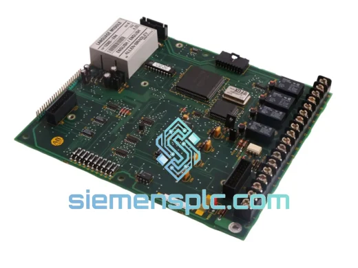
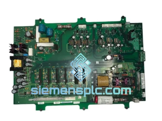
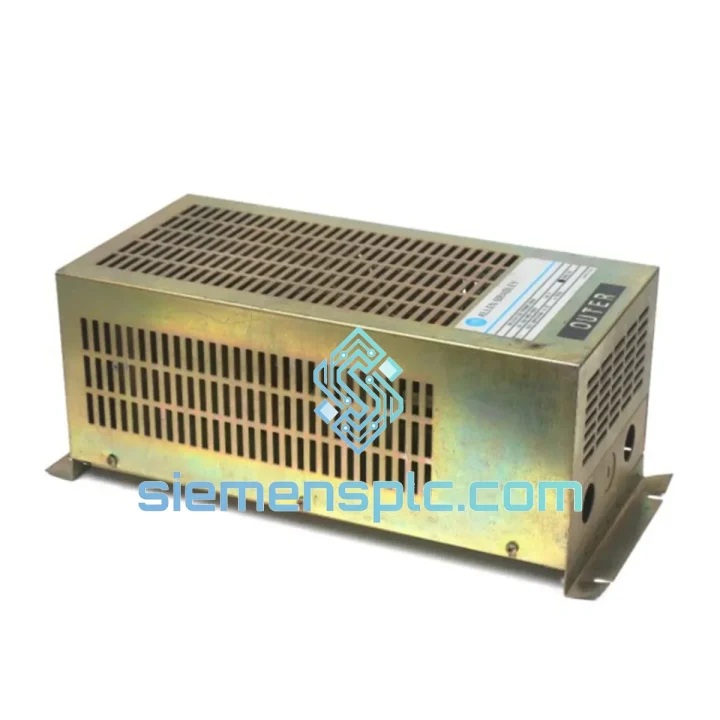
Allen-Bradley 1336-BDB-SP17C 74101-482-51 PC Board – 1336 PLUS
1336 PLUS
Origin US
AC Drive Spare Parts
Request verified availability, condition, replacement risk review, packing options and courier lead time for 1336-MOD-KB010.
Click Request Quote and the part number is inserted into the inquiry form automatically.
Core fields for model confirmation and RFQ routing. Detailed product narrative remains below.
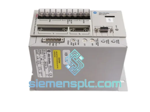
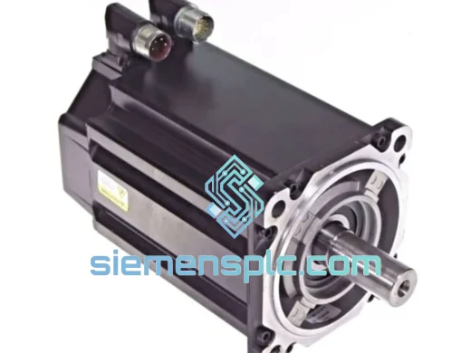
The Allen-Bradley 1336-MOD-KB010 is a factory-engineered dynamic brake option module developed for the 1336 PLUS and 1336 PLUS II families of variable-frequency AC drives manufactured by Rockwell Automation. Its primary function within the drive control loop is to clamp DC bus voltage during deceleration events by routing regenerative energy — generated when a motor acts as a generator under load inertia — through an external braking resistor network. Without this module, rapid deceleration of high-inertia loads such as centrifuges, hoists, or large conveyor systems would cause the DC bus voltage to rise beyond the drive’s overvoltage trip threshold (typically 810 VDC on a 480 VAC input system), resulting in nuisance faults or hardware damage.
The 1336-MOD-KB010 integrates directly into the designated option slot on the 1336 PLUS / PLUS II drive chassis, requiring no external control wiring to the drive’s main control board. The module’s internal IGBT chopper transistor switches the braking resistor across the DC bus when bus voltage exceeds a factory-set threshold, dissipating kinetic energy as heat. This architecture keeps the drive operational through aggressive deceleration ramps without requiring a regenerative front-end or active rectifier — a cost-effective solution for applications where braking duty cycles are intermittent rather than continuous.
📧 Real-time Stock & RFQ: [email protected] | 📱 WhatsApp: +86 18359268345
| Parameter | Specification |
|---|---|
| Manufacturer | Allen-Bradley (Rockwell Automation) |
| Part Number | 1336-MOD-KB010 |
| Module Classification | Dynamic Brake Option Module |
| Compatible Drive Platform | 1336 PLUS, 1336 PLUS II |
| Mounting Interface | Internal option slot (drive-chassis integrated) |
| DC Bus Voltage Range | Nominal 650 VDC (480 VAC input system) |
| Chopper Activation Threshold | Factory-set overvoltage clamp level per drive firmware |
| Switching Device | Internal IGBT transistor |
| External Resistor Interface | Terminal block connection to external brake resistor assembly |
| Braking Duty Cycle | Intermittent (light-to-moderate; see Rockwell pub. 1336-5.9 for sizing) |
| Communication Interface | None (hardware-only module) |
| Approximate Weight | 7.5 kg (including packaging) |
| Country of Origin | United States |
| Warranty | 12 months from date of shipment |
The 1336-MOD-KB010 operates on a threshold-triggered chopper topology. When the DC bus voltage — monitored continuously by the drive’s internal voltage sensing circuit — crosses the programmed overvoltage clamp point, the module’s gate driver fires the IGBT, connecting the external braking resistor across the positive and negative DC bus rails. The resistor then absorbs the regenerative current as thermal energy. Once bus voltage drops below the hysteresis band, the IGBT turns off and the resistor is disconnected.
From an EMC standpoint, the high-frequency switching of the IGBT generates conducted and radiated emissions on the DC bus. The 1336 PLUS drive chassis incorporates internal bus capacitance and snubber networks that attenuate these transients, preventing interference with the drive’s own control electronics and connected field devices. The option slot interface also provides galvanic isolation between the module’s gate drive circuitry and the drive’s low-voltage control logic, protecting the microprocessor-based control board from bus-side voltage spikes during chopper operation.
The module’s thermal design relies on the external resistor to carry the bulk of the energy dissipation load. This deliberate architecture keeps the module itself compact and thermally stable within the drive enclosure, while the resistor — mounted externally with adequate airflow — handles the thermal burden. Engineers should size the resistor according to the peak braking current (derived from motor rated current and deceleration ramp) and the required duty cycle, referencing Rockwell publication 1336-5.9 for validated resistor selection tables. Undersizing the resistor leads to thermal runaway; oversizing increases cost without functional benefit.
The IGBT within the module is rated for the full DC bus voltage of the 480 VAC drive system, with appropriate voltage derating margins built into the design. This ensures reliable switching even under worst-case bus voltage conditions, such as those encountered during utility voltage swell events combined with regenerative loading.
Every Allen-Bradley 1336-MOD-KB010 unit dispatched from our Xiamen, China facility is sourced from verified industrial supply channels and undergoes a pre-shipment inspection protocol covering physical integrity, connector condition, and label authenticity verification against Rockwell Automation’s published part marking standards. Units are supplied in anti-static packaging with desiccant inserts to prevent moisture ingress during transit.
Our logistics infrastructure supports air freight, sea freight, and express courier (DHL, FedEx, UPS) to destinations across Southeast Asia, the Middle East, Europe, and the Americas. Standard air freight transit times from Xiamen to major industrial hubs are 3–7 business days. Full export documentation — including commercial invoice, packing list, certificate of origin, and HS code declaration (HS 8537.10) — is prepared for every international shipment to facilitate smooth customs clearance. For time-critical plant shutdowns or emergency maintenance scenarios, same-day dispatch is available for in-stock units upon order confirmation before 14:00 CST.
A 12-month warranty covers all units against manufacturing defects and functional failure under normal operating conditions. Warranty claims are processed with a target response time of 24 hours, and replacement units are dispatched via express courier to minimize plant downtime.
📧 Email: [email protected]
📱 WhatsApp: +86 18359268345
🌐 Web: siemensplc.com
📍 Location: Xiamen, China
© 2026 siemensplc.com. All rights reserved.
We check the full part number, brand, series and visible nameplate information before quotation.
Sales confirms stock path, condition option, quantity and realistic lead time for export dispatch.
DHL, FedEx, UPS or buyer courier arrangements can be reviewed with packing requirements.
Similar brand or category products for fast comparison and multi-item RFQ lists.