Allen-Bradley
RFQ Ready
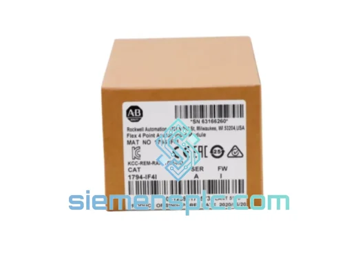
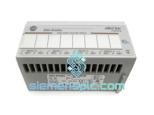
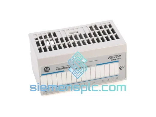
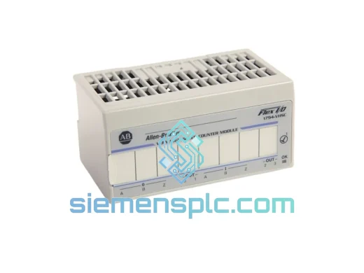
Allen-Bradley 1794-VHSC High Speed Counter Module – FLEX I/O
Flex I/O
Origin US
High Speed Counter Module
Request verified availability, condition, replacement risk review, packing options and courier lead time for 1794-CE1.
Click Request Quote and the part number is inserted into the inquiry form automatically.
Core fields for model confirmation and RFQ routing. Detailed product narrative remains below.
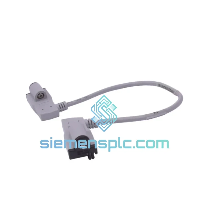
The 1794-CE1 is a factory-terminated backplane extension cable engineered for the Rockwell Automation 1794 FLEX I/O platform. Its primary function is to physically decouple the I/O adapter module from its terminal base assembly, allowing panel designers to reposition the adapter within the enclosure without altering the electrical topology of the FLEX I/O backplane bus. This capability is not cosmetic — it directly addresses a recurring constraint in high-density control panel design where DIN rail space, thermal management zones, and cable tray routing impose strict geometric limits on component placement.
In a standard FLEX I/O node, the adapter module mounts directly onto the terminal base, forming a rigid mechanical and electrical assembly. The 1794-CE1 inserts between these two elements, maintaining the full backplane bus signal path while introducing a controlled physical offset. The cable preserves the impedance characteristics and signal timing of the native backplane interface, which is critical for maintaining deterministic communication between the adapter and downstream I/O modules in the node.
This component is specified by controls engineers across process industries, discrete manufacturing, and infrastructure applications wherever the FLEX I/O platform is deployed in space-constrained or thermally sensitive enclosures. Its value is not in added functionality but in preserving system architecture integrity when physical constraints would otherwise force a redesign of the entire I/O node layout.
Real-time Stock & RFQ: [email protected] | WhatsApp: +86 18359268345
| Part Number | 1794-CE1 |
| Manufacturer | Allen-Bradley / Rockwell Automation |
| Series | FLEX I/O — 1794 Platform |
| Component Classification | Backplane Extender Cable |
| Compatible System | 1794 FLEX I/O Terminal Base and Adapter Assemblies |
| Interface Type | FLEX I/O proprietary backplane bus connector |
| Connector Termination | Factory-crimped, keyed, polarized |
| Signal Path | Full backplane bus — power, data, and control lines |
| Operating Temperature | 0 °C to +60 °C (IEC 60068-2-1/2) |
| Storage Temperature | -40 °C to +85 °C |
| Relative Humidity | 5% to 95% non-condensing |
| Vibration Resistance | Per IEC 60068-2-6 (sinusoidal) |
| Shock Resistance | Per IEC 60068-2-27 |
| Certifications | UL Listed, CE Marked, RoHS Compliant |
| Country of Origin | United States |
| Product Condition | Genuine New / Surplus New |
| Warranty | 12 months against manufacturing defects |
| Weight (approx.) | 300 g |
The FLEX I/O backplane is not a passive wire harness — it carries a multiplexed serial communication bus alongside distributed DC power rails. The 1794-CE1 must therefore satisfy two simultaneous engineering requirements: maintain the electrical integrity of a time-sensitive data bus and carry sufficient current capacity for the power distribution function without introducing resistive drop that would violate the platform’s voltage budget.
Connector Keying and Polarization: The cable uses mechanically keyed, polarized connectors at both terminations. This prevents reverse insertion, which would short the backplane power rails — a failure mode that can damage the adapter module, the terminal base, and any I/O modules already installed in the node. The keying geometry is unique to the 1794 platform, making cross-platform misconnection physically impossible.
Impedance Continuity: The FLEX I/O backplane bus operates at signal frequencies where cable impedance discontinuities produce reflections that corrupt data frames. The 1794-CE1 uses a controlled-impedance cable construction with matched characteristic impedance to the native backplane traces. This ensures that the insertion of the extender does not introduce standing wave effects or increase bit error rates in the adapter-to-module communication path.
EMC Shielding Architecture: Industrial panel environments expose cables to conducted and radiated electromagnetic interference from variable frequency drives, contactors, and high-current switching loads. The 1794-CE1 incorporates a braided shield layer with defined drain wire termination at the connector shells. This provides a low-impedance return path for induced common-mode currents, preventing them from coupling into the differential signal pairs of the backplane bus. The shield termination strategy follows IEC 61000-4-3 radiated immunity test methodology.
Power Rail Current Capacity: The backplane power conductors within the cable are sized to carry the full current demand of the adapter module plus any bus-powered I/O modules in the node. The conductor cross-section is selected to maintain voltage drop within the tolerance band specified in the 1794 FLEX I/O System User Manual (Publication 1794-UM001), ensuring that downstream modules receive supply voltage within their operating range under worst-case load conditions.
Mechanical Strain Relief: Both connector housings incorporate integral strain relief features that clamp the cable jacket independently of the conductor terminations. This prevents tensile loads from being transmitted to the crimp joints, which is the primary failure mechanism for field-fabricated cables in high-vibration environments. The factory-applied strain relief meets the pull-force requirements of IEC 60352-2 for crimped connections.
Every 1794-CE1 unit supplied by siemensplc.com is sourced through verified channels and subjected to a structured incoming inspection process before dispatch. Visual inspection covers connector housing integrity, cable jacket condition, label legibility, and factory seal status. Each unit is cross-referenced against the Rockwell Automation part number database to confirm authenticity and revision level.
Packaging uses anti-static bags with humidity indicator cards, enclosed in rigid corrugated cartons with foam insert protection. This packaging specification is designed for long-haul air freight from Xiamen, China, where temperature and humidity variations during transit can affect sensitive electronic components if packaging is inadequate.
Shipments originate from our Xiamen warehouse and are dispatched via DHL Express, FedEx International Priority, and UPS Worldwide Expedited, with typical transit times of 3–7 business days to major industrial hubs in Europe, North America, Southeast Asia, and the Middle East. For urgent requirements, same-day dispatch is available on in-stock units when orders are confirmed before 14:00 CST.
Lot traceability documentation, including Certificate of Conformance and country of origin declarations, is available upon request and is routinely provided for customers in regulated industries such as pharmaceutical manufacturing, nuclear power, and aerospace ground support. A 12-month warranty against manufacturing defects applies to all new units. Surplus-new units carry a 90-day functional warranty with return authorization support.
Email: [email protected]
WhatsApp: +86 18359268345
Web: siemensplc.com
Location: Xiamen, China
© 2026 siemensplc.com. All rights reserved.
We check the full part number, brand, series and visible nameplate information before quotation.
Sales confirms stock path, condition option, quantity and realistic lead time for export dispatch.
DHL, FedEx, UPS or buyer courier arrangements can be reviewed with packing requirements.
Similar brand or category products for fast comparison and multi-item RFQ lists.