Bently Nevada
RFQ Ready
Bently Nevada 21000-34-10-00-085-04-02 Proximity Probe Housing Assembly
21000 Series
Origin US
Proximity Probe Housing Assembly
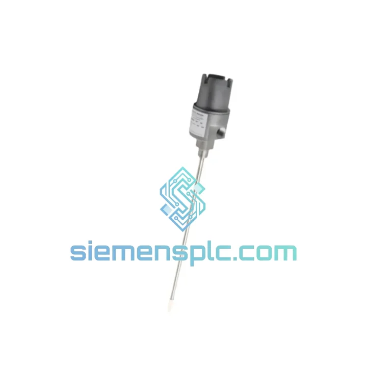
Request verified availability, condition, replacement risk review, packing options and courier lead time for 21000-00-00-00-250-03-02.
Click Request Quote and the part number is inserted into the inquiry form automatically.
Core fields for model confirmation and RFQ routing. Detailed product narrative remains below.
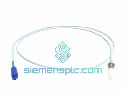
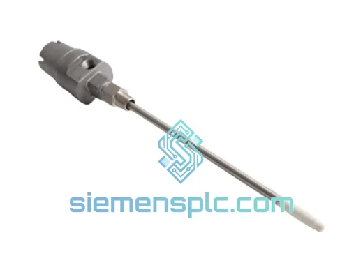
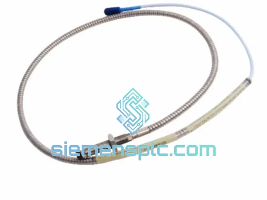
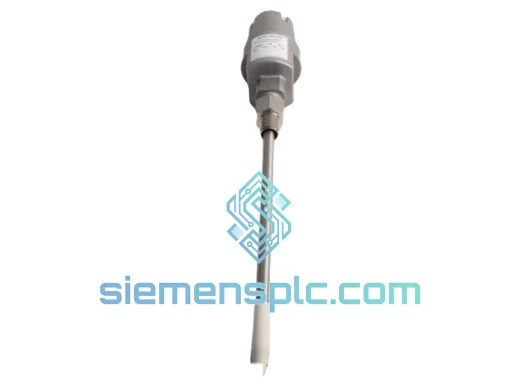
The Bently Nevada 21000-00-00-00-250-03-02 is an 8 mm eddy current proximity probe with a 2.5 m integral armored cable, engineered for continuous, non-contact measurement of radial shaft vibration, axial thrust position, and differential expansion in critical rotating machinery. Within a machinery protection loop, this probe functions as the primary transducer: it converts the physical gap between probe tip and target shaft into a proportional DC voltage signal, which is then conditioned by a matched driver/extension cable system before being processed by a Bently Nevada 3300 XL or 3500 Series monitoring rack.
The operating principle is based on Faraday’s law of electromagnetic induction. A high-frequency oscillator (typically 1.0 MHz) within the driver energizes a coil wound at the probe tip. When a conductive ferromagnetic target enters the probe’s electromagnetic field, eddy currents are induced on the target surface, loading the oscillator circuit and reducing its output amplitude. This amplitude change is demodulated and scaled to produce a linear DC output of approximately −18 VDC at the nominal gap, with a scale factor of 200 mV/mil (7.87 V/mm). The 21000 series is factory-calibrated against AISI 4140 steel targets; for non-standard shaft materials such as 17-4 PH stainless or titanium alloys, a material correction factor must be applied at the monitoring rack.
The 2.5 m cable designation in the part number (position 5: “250”) defines the integral cable length from probe body to connector. This length is a fixed system parameter: the total electrical length of probe plus extension cable must match the driver’s calibrated range to maintain the specified scale factor within ±1%. Substituting a different cable length without recalibrating the driver will introduce a systematic measurement error that cannot be corrected by rack gain adjustment alone.
Real-time Stock & RFQ: [email protected] | WhatsApp: +86 18359268345
| Part Number | 21000-00-00-00-250-03-02 |
| Brand | Bently Nevada (Baker Hughes) |
| Series | 21000 Proximity Probe Series |
| Probe Type | Eddy Current, Non-Contact |
| Tip Diameter | 8 mm |
| Integral Cable Length | 2.5 m (250 cm) |
| Connector | Integral coaxial, BNC-compatible termination |
| Oscillator Frequency | ~1.0 MHz (driver-dependent) |
| Nominal Output Voltage | −18 VDC at calibrated gap |
| Scale Factor | 200 mV/mil (7.87 V/mm) ±1% |
| Linear Range | 0.25 mm to 2.25 mm (10 mil to 90 mil) |
| Target Material (Standard) | AISI 4140 Steel (ferromagnetic) |
| Supply Voltage | −24 VDC (via driver) |
| Operating Temperature | −35°C to +120°C |
| Ingress Protection | IP67 |
| Approx. Weight (with cable) | 1,100 g |
| Compliance Standards | API 670, CE |
| Compatible Monitoring Systems | Bently Nevada 3300 XL, 3500, ADAPT 3701 |
| Warranty | 12 months against manufacturing defects |
| Country of Origin | United States |
Electromagnetic Field Geometry and Gap Linearity: The 8 mm tip diameter of the 21000 series defines the effective sensing area and directly governs the linear measurement range. A smaller tip diameter concentrates the electromagnetic field, reducing the linear range but improving spatial resolution for small-diameter shafts. The 8 mm geometry is optimized for shaft diameters of 50 mm and above, where the ratio of probe tip area to shaft curvature remains within the linearity specification. The probe body is machined from non-magnetic stainless steel to prevent the housing from perturbing the field pattern, which would introduce a fixed offset error indistinguishable from a real gap change.
EMC Design and Shielding Architecture: The integral cable uses a double-layer coaxial construction: an inner conductor carries the high-frequency oscillator signal, surrounded by a polytetrafluoroethylene (PTFE) dielectric, then a braided copper shield, and an outer armor jacket. The shield is grounded at the driver end only (single-point grounding) to prevent ground loop currents from coupling noise onto the signal conductor. In environments with high-frequency switching drives (e.g., variable frequency drives operating at 4–16 kHz PWM), the armor jacket provides an additional Faraday shield against capacitively coupled interference. The probe tip assembly is hermetically sealed with an epoxy compound rated to IP67, preventing moisture ingress that would alter the dielectric constant of the tip medium and shift the calibration curve.
Thermal Stability and Calibration Drift: The oscillator coil at the probe tip is wound with a controlled number of turns on a ferrite core with a low temperature coefficient of permeability. Over the operating range of −35°C to +120°C, the scale factor drift is specified at less than ±0.5% of full scale per 50°C change. In steam turbine exhaust-side installations where probe body temperatures can approach 110°C continuously, this thermal stability is a critical design parameter. The driver electronics compensate for cable capacitance changes with temperature, maintaining the overall system accuracy within the API 670 requirement of ±1% of full-scale output.
Mechanical Mounting and Thread Specification: The probe body incorporates a standard metric thread (M10×1.0 or M14×1.5 depending on the mounting bracket configuration) with a locknut for positional fixation after gap setting. The gap is set mechanically using a feeler gauge or a DC voltmeter reading the driver output: at the nominal −18 VDC output, the gap corresponds to the midpoint of the linear range, providing equal measurement headroom for both inward and outward shaft displacement. The armored cable is strain-relieved at the probe body exit point with a stainless steel ferrule to prevent flex fatigue at the highest mechanical stress concentration.
Every 21000-00-00-00-250-03-02 unit supplied by siemensplc.com is sourced directly from Bently Nevada (Baker Hughes) authorized distribution channels. Each probe ships with its original factory packaging, a calibration certificate with NIST-traceable data, and a factory test report confirming scale factor, linearity, and OK circuit function. Units are inspected upon receipt at our Xiamen, China warehouse for physical integrity, label authenticity, and documentation completeness before being allocated to customer orders.
Our Xiamen location provides direct access to Xiamen Gaoqi International Airport (XMN) and the Port of Xiamen, two of China’s primary export hubs for industrial components. Standard export documentation — commercial invoice, packing list, certificate of origin, and material safety data sheet — is prepared for every shipment. For customers requiring expedited delivery, DHL Express and FedEx International Priority services from Xiamen typically achieve transit times of 3–5 business days to major industrial centers in Europe, North America, Southeast Asia, and the Middle East. Sea freight consolidation is available for bulk orders where lead time permits.
All units carry a 12-month warranty against manufacturing defects from the date of shipment. Warranty claims are processed with replacement unit dispatch within 5 business days upon receipt of the defective unit and supporting documentation. Export compliance screening is performed on every order in accordance with applicable export control regulations.
Email: [email protected]
WhatsApp: +86 18359268345
Web: siemensplc.com
Location: Xiamen, China
© 2026 siemensplc.com. All rights reserved.
We check the full part number, brand, series and visible nameplate information before quotation.
Sales confirms stock path, condition option, quantity and realistic lead time for export dispatch.
DHL, FedEx, UPS or buyer courier arrangements can be reviewed with packing requirements.
Similar brand or category products for fast comparison and multi-item RFQ lists.