Bently Nevada
RFQ Ready
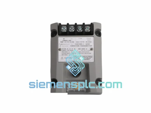
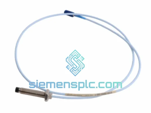
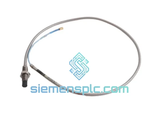
Bently Nevada RS901104-03-050-10-01 Proximitor Sensor – 3300 XL Series
3300 XL
Origin US
Proximitor Sensor
Request verified availability, condition, replacement risk review, packing options and courier lead time for 21000-16-05-00-040-03-02.
Click Request Quote and the part number is inserted into the inquiry form automatically.
Core fields for model confirmation and RFQ routing. Detailed product narrative remains below.
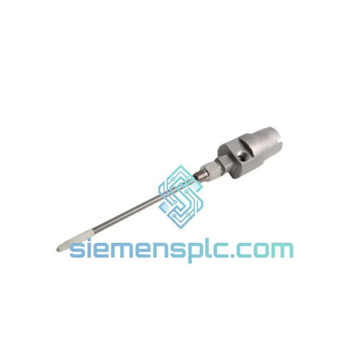
The 21000-16-05-00-040-03-02 is a precision-machined proximity probe housing assembly manufactured by Bently Nevada for permanent integration into the 3300 XL Proximity Transducer System. Its mechanical function is singular and non-negotiable: hold the probe tip at a repeatable axial standoff from the observed shaft surface so that the eddy-current driver operates within its calibrated linear band. Positional repeatability across installation cycles is maintained to within ±0.05 mm, which corresponds to a gap-voltage repeatability of approximately ±0.39 VDC on an 8 mm probe with a nominal sensitivity of –7.87 V/mm.
The housing is threaded to 5/16-28 UNF, matching the probe body thread geometry standardized across the 3300 XL family. The external boss dimensions conform to API 670, Fifth Edition, mechanical interface requirements, allowing direct installation into OEM-drilled bearing housing bosses on turbines, centrifugal compressors, and boiler feed pumps without secondary machining. The locknut arrangement permits ±0.5 mm of axial adjustment at installation, providing sufficient range to compensate for machining tolerances in the bearing housing boss depth while keeping the probe tip within the driver’s –2 VDC to –18 VDC linear output window.
Real-time Stock & RFQ: [email protected] | WhatsApp: +86 18359268345
| Parameter | Specification |
|---|---|
| Part Number | 21000-16-05-00-040-03-02 |
| Manufacturer | Bently Nevada (Baker Hughes) |
| Compatible System | 3300 XL Proximity Transducer System |
| Probe Thread | 5/16-28 UNF |
| Housing Material | 316L Stainless Steel |
| Probe Tip Standoff Repeatability | ±0.05 mm across installation cycles |
| Axial Adjustment Range (locknut) | ±0.5 mm |
| Nominal Gap Voltage (8 mm probe) | –10 VDC at 1.0–1.5 mm air gap |
| Driver Linear Output Range | –2 VDC to –18 VDC |
| Probe Sensitivity (8 mm) | –7.87 V/mm (nominal) |
| Compatible Probe Diameters | 8 mm, 11 mm (3300 XL series) |
| Operating Temperature Range | –50 °C to +120 °C (probe tip environment) |
| Housing CTE | ~16 µm/m·°C (316L SS) |
| Assembly Weight | 1,400 g |
| Compliance Standards | API 670 (5th Ed.), CE (2014/30/EU), RoHS |
| Warranty | 12 months against manufacturing defects |
The 3300 XL transducer chain operates on the eddy-current induction principle. A high-frequency oscillator embedded in the driver module — typically running at 1.0 MHz carrier frequency — energizes the probe coil through a coaxial extension cable. When the probe tip approaches a conductive shaft surface, eddy currents are induced in the shaft material, loading the probe coil and reducing its effective impedance. The driver demodulates this impedance change into a DC voltage output proportional to the probe-to-shaft gap distance. The housing assembly’s contribution to this signal chain is entirely mechanical, yet its dimensional precision governs the accuracy of every measurement the system produces.
Standoff geometry and sensitivity curve positioning: The 21000-16-05-00-040-03-02 positions the probe tip at the designed installation depth with ±0.05 mm axial tolerance. On the 8 mm probe sensitivity curve, a 0.05 mm positional error introduces a static gap-voltage offset of approximately 0.39 VDC. This offset is indistinguishable from a real shaft displacement event at the driver output and cannot be corrected in the monitor rack without re-gapping. The housing’s dimensional precision therefore directly determines the zero-error floor of the entire measurement loop.
EMC shielding continuity through the bearing housing interface: The 316L stainless-steel body forms a continuous conductive enclosure from the probe cable entry to the bearing housing boss face. This extends the coaxial cable’s outer shield into the bearing housing structure, attenuating capacitively coupled interference from adjacent power conductors. In turbine halls where 6 kV switchgear, variable-frequency drives, and excitation systems operate within 2–5 m of the transducer chain, this shielding continuity is the primary defense against common-mode noise injection into the measurement signal. Without it, noise floor degradation of 5–15 mV RMS is typical, which at –7.87 V/mm sensitivity corresponds to an apparent shaft vibration of 0.6–1.9 µm — sufficient to generate nuisance alarms on tightly set alert thresholds.
Thermal differential expansion at the bearing housing interface: 316L stainless steel has a coefficient of thermal expansion of approximately 16 µm/m·°C. Carbon-steel bearing housings typically exhibit a CTE of 11–12 µm/m·°C. Over a 40 mm housing length and a 100 °C temperature differential between cold-start and full-load bearing temperature, the differential expansion between housing and bearing housing boss is approximately 16 µm. This is within the ±0.5 mm locknut adjustment range but must be accounted for during hot-gap verification at commissioning. Engineers should record gap voltage at both ambient and operating temperature to establish a thermal correction baseline for each channel.
Corrosion resistance in aggressive process environments: The molybdenum content of 316L (2.0–3.0 wt%) provides pitting resistance in chloride-bearing atmospheres with a pitting resistance equivalent number (PREN) of approximately 24–26. This makes the housing suitable for offshore platform installations, coastal power stations, and LNG liquefaction facilities where salt-laden air contacts the bearing housing exterior. The low-carbon variant (316L vs. 316) also resists sensitization during welding operations performed on adjacent bearing housing structures.
Each 21000-16-05-00-040-03-02 unit dispatched from siemensplc.com passes a structured incoming inspection protocol before packaging:
All orders are dispatched from our warehouse in Xiamen, China. DHL Express and FedEx International Priority shipments reach most global destinations in 3–7 business days. Same-day dispatch is available for orders confirmed before 14:00 CST. Each shipment includes a complete customs package: commercial invoice, packing list, and HS code 9026.80 declaration to minimize clearance delays at destination ports. Air freight tracking numbers are provided within 2 hours of dispatch.
Email: [email protected]
WhatsApp: +86 18359268345
Web: siemensplc.com
Location: Xiamen, China
© 2026 siemensplc.com. All rights reserved.
We check the full part number, brand, series and visible nameplate information before quotation.
Sales confirms stock path, condition option, quantity and realistic lead time for export dispatch.
DHL, FedEx, UPS or buyer courier arrangements can be reviewed with packing requirements.
Similar brand or category products for fast comparison and multi-item RFQ lists.