Bently Nevada
RFQ Ready
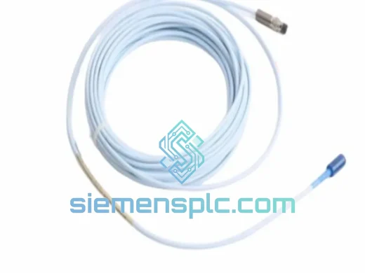
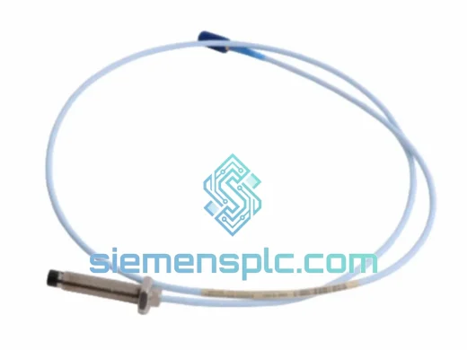
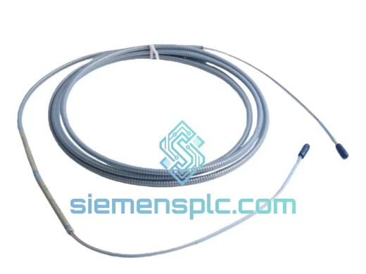
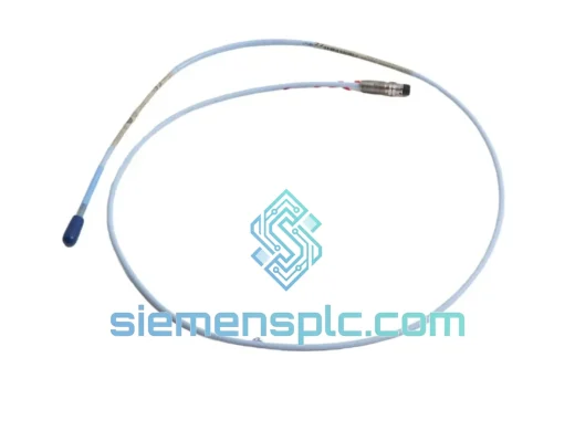
Bently Nevada 330196-05-30-10-00 Proximity Probe – 3300 XL ETR
3301
Origin US
Proximity Probe
Request verified availability, condition, replacement risk review, packing options and courier lead time for 330101-00-12-10-12-CN.
Click Request Quote and the part number is inserted into the inquiry form automatically.
Core fields for model confirmation and RFQ routing. Detailed product narrative remains below.
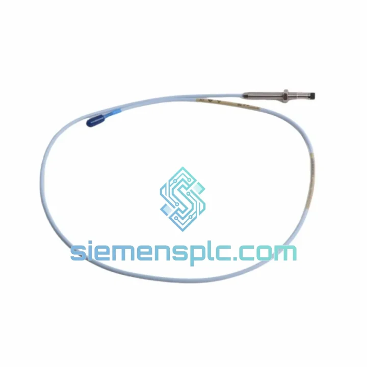
The Bently Nevada 330101-00-12-10-12-CN is a complete eddy-current proximity transducer system within the 3300 XL Series, engineered for continuous, non-contact measurement of radial shaft vibration, axial position, and differential eccentricity in critical rotating machinery. The part number encodes the full system geometry: 8 mm probe body diameter, 1.0 m integral armored cable, 1.0 m extension cable, 12 m total system length from probe tip to Proximitor driver output terminal, and a CN-standard connector termination optimized for Chinese domestic field wiring practice. This is not a standalone probe — it is a factory-calibrated, matched-assembly system in which the probe coil, cable impedance, and Proximitor driver gain network are trimmed as a unit to achieve the specified output accuracy.
The operating principle is electromagnetic induction. The Proximitor driver excites the probe coil at approximately 1.0 MHz, establishing a focused oscillating magnetic field at the probe face. When a conductive ferromagnetic target — standardly AISI 4140 steel per API 670 calibration protocol — enters the field, eddy currents are induced within a surface layer whose penetration depth is governed by the skin-effect relationship δ = √(ρ / πfμ). At 1.0 MHz excitation frequency and the conductivity of AISI 4140, the effective skin depth is approximately 0.08 mm. This confines the measurement interaction to the shaft surface layer, making the output insensitive to subsurface material inhomogeneities, internal voids, or residual stress gradients that would affect contact-type displacement sensors. The induced eddy currents load the oscillator tank circuit, reducing its Q-factor in a monotonic, near-linear relationship with gap distance. The driver’s demodulator extracts this amplitude envelope and converts it to a DC output voltage with a nominal sensitivity of 7.87 V/mm (200 mV/mil), spanning −2 VDC to −18 VDC across the calibrated linear range of 0.25 mm to 2.54 mm (10 mil to 100 mil).
The -CN connector designation specifies a bayonet-lock connector body geometry and locking mechanism matched to Chinese-manufactured junction boxes and marshalling panels. Electrically, the CN variant is fully equivalent to the international configuration. The mechanical adaptation eliminates field-fabricated adapter assemblies that introduce additional contact resistance, potential intermittent connections, and unverified impedance discontinuities in the signal path — each of which degrades measurement integrity in ways that are difficult to distinguish from genuine shaft dynamic events during post-event analysis.
Factory calibration is performed on the complete system — probe, integral cable, extension cable, and Proximitor driver — as a matched assembly. The driver’s internal gain-setting resistor network is laser-trimmed to compensate for the specific impedance of the probe-cable combination, achieving output linearity within ±0.05 mm across the full linear range. This matched-system architecture is a technical requirement of API 670 Fifth Edition Section 5.3, which mandates that transducer system accuracy be verified on the complete assembly rather than on individual components. Field substitution of any element without recalibration introduces a systematic offset that cannot be corrected by monitor zero/span trimming alone, and which may cause the protection system to operate at an effective trip setpoint different from the configured value.
In turbomachinery protection applications, the 330101-00-12-10-12-CN is typically deployed in pairs at each radial bearing plane, oriented at 90° to each other (X–Y configuration), to enable shaft orbit reconstruction. The orbit plot — a Lissajous figure of X-displacement versus Y-displacement — is the primary diagnostic tool for distinguishing between synchronous imbalance, oil-film instability (whirl and whip), misalignment, and rub contact. The 12 m total system length accommodates installations where the Proximitor driver must be located outside the bearing housing thermal zone, in a remote junction box or instrument enclosure, without degrading measurement bandwidth or sensitivity.
Real-time Stock & RFQ: [email protected] | WhatsApp: +86 18359268345
| Parameter | Specification |
|---|---|
| Part Number | 330101-00-12-10-12-CN |
| Brand | Bently Nevada (Baker Hughes) |
| Series | 3300 XL |
| Sensing Principle | Eddy-current, non-contact inductive |
| Probe Tip Diameter | 8 mm |
| Mounting Thread | M10 × 1.0 |
| Probe Body Material | 316L Stainless Steel |
| Integral Cable Length | 1.0 m (armored) |
| Extension Cable Length | 1.0 m |
| Total System Length | 12 m (probe tip to Proximitor output terminal) |
| Connector Standard | CN (Chinese domestic bayonet-lock) |
| Supply Voltage | −24 VDC nominal; −20 VDC to −26 VDC operating range |
| Output Voltage Range | −2 VDC to −18 VDC |
| Sensitivity | 7.87 V/mm (200 mV/mil) |
| Calibrated Linear Range | 0.25 mm – 2.54 mm (10 mil – 100 mil) |
| Linearity Error | ≤ ±0.05 mm over full linear range |
| Frequency Response (−3 dB) | DC to 10,000 Hz |
| Oscillator Excitation Frequency | ~1.0 MHz |
| Output Impedance | 100 Ω nominal |
| Supply Current | ≤ 12 mA per channel |
| Probe Operating Temperature | −35 °C to +177 °C |
| Driver Operating Temperature | −35 °C to +85 °C |
| Target Material (standard calibration) | AISI 4140 steel |
| Ingress Protection (probe) | IP67 |
| Compliance Standards | API 670 Fifth Edition, CE, RoHS |
| Probe Assembly Weight | ~80 g |
| Warranty | 12 months from shipment date |
Guard-Driven Coaxial Cable and Distributed Capacitance Cancellation: The coaxial cable connecting probe to Proximitor driver employs a guard-driven shield topology. The shield conductor is driven at the same potential as the center conductor through a unity-gain buffer internal to the driver. This bootstrapping arrangement eliminates the distributed cable capacitance as a shunt path for the 1.0 MHz oscillator signal. Without guard driving, a 12 m coaxial cable presents approximately 1.2 nF of distributed capacitance — sufficient to attenuate the oscillator amplitude by several percent and introduce measurable phase shift at frequencies above 5 kHz. With guard driving active, the effective shunt capacitance is reduced to the residual guard-to-outer-shield capacitance, typically below 50 pF, preserving full sensitivity and frequency response at the specified 12 m system length.
Tank Circuit Q-Factor and Linearity Mechanism: The Proximitor driver’s LC oscillator tank circuit operates at a nominal unloaded Q-factor of 80–120, determined by the probe coil geometry and the fixed capacitor bank. As the conductive target approaches the probe face, eddy-current losses reduce the effective Q in a relationship that is monotonic but inherently nonlinear over a wide gap range. The driver’s demodulator and output amplifier incorporate a piecewise-linear correction network — implemented as a resistor-diode ladder — that compensates the inherent nonlinearity of the Q-versus-gap transfer function, producing the specified ±0.05 mm linearity across the 0.25 mm to 2.54 mm calibrated range. The correction coefficients are set during matched-system calibration and are specific to the probe-cable combination; this is the technical basis for the API 670 requirement that the complete system be calibrated as an assembly.
EMC Architecture in High-Interference Industrial Environments: Turbine halls and compressor stations present electromagnetic environments characterized by variable-frequency drive switching transients (dV/dt up to 10 kV/μs), strong 50/60 Hz magnetic fields from adjacent motor windings, and RF interference from wireless instrumentation networks. The 3300 XL Proximitor driver’s input stage uses a differential topology with a common-mode rejection ratio (CMRR) exceeding 60 dB at 50/60 Hz, attenuating power-frequency interference induced on the cable shield. The fluoropolymer (FEP) cable jacket provides dielectric isolation rated to 600 V, preventing capacitive coupling from adjacent high-voltage cables in shared conduit runs. The probe body’s 316L stainless steel construction provides magnetic shielding of the coil assembly against low-frequency external fields that would otherwise modulate the oscillator operating point.
Thermal Sensitivity Compensation Network: The probe coil is wound with a temperature-stable alloy selected for a low temperature coefficient of resistance (TCR). The Proximitor driver supplements this with a thermistor-based compensation network that adjusts demodulator gain as a function of measured driver ambient temperature. Across the probe’s full operating range of −35 °C to +177 °C, the combined compensation holds sensitivity drift within ±0.5% of full scale — equivalent to ±0.013 mm at the midpoint of the linear range. For steam turbine applications where probe tip temperatures routinely reach 140–160 °C during loaded operation, this compensation is the mechanism that maintains alarm and trip setpoint accuracy without periodic field recalibration between planned maintenance outages.
CN Connector Contact Integrity and Vibration Resistance: The CN bayonet-lock connector uses gold-plated contacts with a contact resistance specification of ≤ 5 mΩ per mating pair, rated for 500 insertion cycles. Gold plating prevents oxide film formation that would introduce variable contact resistance and low-frequency noise in the output signal — noise that is indistinguishable from low-amplitude shaft motion at the monitor input. The bayonet locking mechanism provides a positive tactile indication of full engagement and resists vibration-induced loosening under IEC 60068-2-6 vibration profiles up to 50 g peak, a requirement for installations on or adjacent to reciprocating compressor frames.
Every Bently Nevada 330101-00-12-10-12-CN unit dispatched from siemensplc.com passes a structured three-stage incoming inspection before release to stock. Stage one covers physical integrity: connector body condition, cable jacket continuity, probe tip surface finish, and thread gauge verification. Stage two covers electrical continuity: probe coil resistance within ±5% of nominal, cable shield isolation ≥ 100 MΩ at 500 VDC test voltage, and center conductor continuity end-to-end. Stage three covers functional output verification: DC output voltage at a fixed reference gap is compared against the factory calibration curve, with an acceptance criterion of ±2% of nominal sensitivity. Units outside acceptance limits are quarantined and removed from the supply chain without exception or rework.
A Certificate of Conformance (COC) is provided with every shipment. Original factory test reports and calibration certificates are available upon request for projects requiring full traceability to the manufacturer’s quality management system. Third-party witnessed inspection at our Xiamen facility can be arranged for large-volume procurement or projects with owner-engineer hold-point inspection requirements. All units are stored in climate-controlled conditions at 15–25 °C and 30–60% RH to prevent connector oxidation and cable jacket degradation during storage.
Logistics operations are based in Xiamen, China, with direct access to Xiamen Gaoqi International Airport and Xiamen Port for air and sea freight respectively. In-stock orders are processed within 1–2 business days. Express air freight via DHL, FedEx, or UPS delivers to European, North American, and Southeast Asian destinations within 3–5 business days from dispatch. Sea freight LCL consolidation is available for bulk orders with transit times of 18–25 days to major ports. All shipments include cargo insurance, real-time tracking, and a complete export documentation package — commercial invoice, packing list, and certificate of origin — prepared to destination country import requirements. The 12-month warranty from shipment date covers functional failure under normal operating conditions, with warranty claims processed within 5 business days of receipt of the returned unit at our Xiamen facility.
Email: [email protected]
WhatsApp: +86 18359268345
Web: siemensplc.com
Location: Xiamen, China
© 2026 siemensplc.com. All rights reserved.
We check the full part number, brand, series and visible nameplate information before quotation.
Sales confirms stock path, condition option, quantity and realistic lead time for export dispatch.
DHL, FedEx, UPS or buyer courier arrangements can be reviewed with packing requirements.
Similar brand or category products for fast comparison and multi-item RFQ lists.