Bently Nevada
RFQ Ready
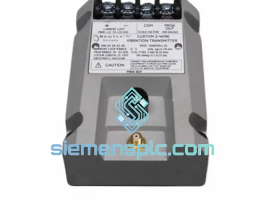
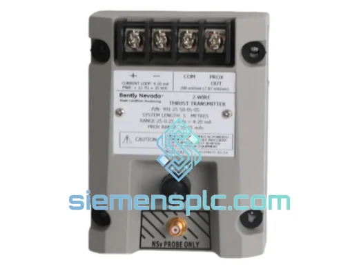
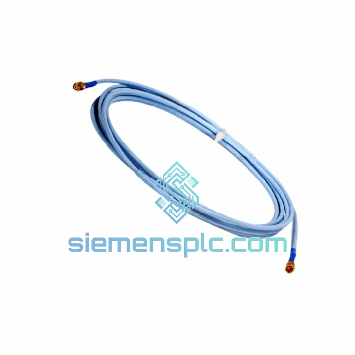
Bently Nevada 991-25-50-01-05 Thrust Position Transmitter – 3300 Proximitor Series
3300 Series
Origin US
Thrust Position Transmitter
Request verified availability, condition, replacement risk review, packing options and courier lead time for 330130-045-01-05.
Click Request Quote and the part number is inserted into the inquiry form automatically.
Core fields for model confirmation and RFQ routing. Detailed product narrative remains below.
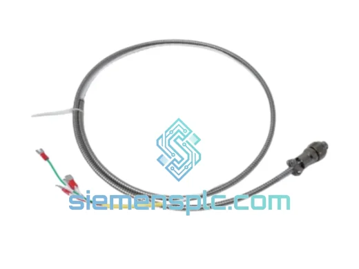
The 330130-045-01-05 is a factory-matched extension cable manufactured by Bently Nevada (Baker Hughes) for exclusive use within the 3300 Series eddy-current measurement chain. Its function is not merely mechanical interconnection — it is a precision electrical component whose capacitance, characteristic impedance, and attenuation profile are trimmed at the factory to integrate with the Proximitor sensor’s internal linearization and temperature-compensation circuitry. Substituting a generic coaxial assembly introduces systematic measurement error that cannot be corrected by field calibration.
In a correctly assembled 3300 XL 8mm system, the 330130-045 (4.5 m extension) pairs with a 0.5 m probe cable to yield the standard 5.0 m total system length — the calibrated baseline for 3300 XL Proximitor sensors (330180, 330181). Deviating from this total length without a corresponding Proximitor recalibration shifts the output voltage-to-gap relationship and degrades measurement accuracy across the full displacement range.
Real-time Stock & RFQ: [email protected] | WhatsApp: +86 18359268345
| Part Number | 330130-045-01-05 |
| Manufacturer | Bently Nevada (Baker Hughes) |
| Platform | 3300 Series Proximitor System |
| Component Role | Extension Cable — Probe-to-Proximitor Signal Interconnect |
| Cable Length | 4.5 m (14.76 ft) |
| Armor Code (-01) | Stainless steel interlocked armor — mechanical protection grade |
| Connector Code (-05) | Standard coaxial, factory-terminated both ends |
| Characteristic Impedance | Matched to 3300 XL Proximitor specification (not a standard 50 Ω or 75 Ω cable) |
| Capacitance | Factory-trimmed; deviation <±2% from nominal to maintain Proximitor compensation accuracy |
| Operating Temperature | −40 °C to +125 °C continuous |
| EMI Shielding | Double-shielded coaxial construction; shield coverage ≥95% |
| Compatible Probes | 330101, 330103, 330104, 330105 (3300 Series 8mm eddy-current probes) |
| Compatible Proximitors | 330180, 330181 (3300 XL 8mm Proximitor Sensor) |
| Standard System Total Length | 5.0 m (0.5 m probe + 4.5 m extension) |
| Regulatory Compliance | CE; ATEX (consult zone classification datasheet) |
| API Standard | API 670 — Machinery Protection Systems |
| Country of Origin | USA |
| Warranty | 12 months from date of shipment |
The 3300 Series measurement chain operates on the eddy-current (inductive proximity) principle. The probe tip generates a high-frequency oscillating electromagnetic field (typically 1.0 MHz carrier). When a conductive target — the rotating shaft — enters this field, eddy currents are induced on the shaft surface, loading the probe’s oscillator circuit and reducing its output amplitude in proportion to the gap distance. This amplitude-modulated RF signal must travel from the probe (mounted at the bearing housing, often in a high-temperature, high-vibration zone) to the Proximitor sensor (mounted remotely in a junction box or instrument rack).
The 330130-045-01-05 performs this transmission with three hardware-level design disciplines:
1. Impedance Matching and Reflection Control: The cable’s characteristic impedance is not a standard telecommunications value. It is specified by Bently Nevada to match the output impedance of the probe oscillator and the input impedance of the Proximitor’s demodulation stage. A mismatch — even a few ohms — creates signal reflections at both terminations. At 1 MHz carrier frequency, these reflections produce standing waves that superimpose on the displacement signal, manifesting as a fixed-frequency noise floor elevation that cannot be filtered without also attenuating the vibration signal of interest.
2. Capacitance Trimming and Linearization Compensation: The Proximitor sensor contains an internal lookup table or analog compensation network calibrated against a specific cable capacitance value. The 330130-045 cable’s capacitance is factory-trimmed to fall within a tight tolerance band. If a replacement cable has higher capacitance (as most generic coaxial cables do), the Proximitor’s compensation network operates outside its design range, introducing a nonlinear offset in the voltage-to-gap transfer function — typically manifesting as a 2–5% span error that worsens at the extremes of the measurement range.
3. EMC Design — Double-Shield Architecture: Industrial environments hosting large rotating machinery are electrically hostile. Variable-frequency drives (VFDs) operating at switching frequencies of 2–16 kHz, high-current bus bars, and RF sources from wireless instrumentation all generate conducted and radiated interference. The 330130’s double-shield construction — an inner braid shield bonded to the connector shell at the Proximitor end, and an outer foil/braid combination — provides two independent attenuation barriers. The inner shield addresses high-frequency radiated pickup; the outer armor provides both mechanical protection and a low-impedance path for low-frequency conducted interference. Ground loops are managed by single-point grounding at the Proximitor end, consistent with API 670 grounding requirements.
4. Armor Integrity Under Mechanical Stress: The -01 armor designation specifies stainless steel interlocked armor applied over the cable jacket. In turbine and compressor installations, cables are routed through cable trays, conduit, and across structural members subject to thermal expansion and vibration. The armor prevents abrasion damage at support points and resists crush loads from cable tray fill. Critically, armor continuity is verified at the factory — a broken armor section that contacts the inner shield creates a ground fault that shifts the Proximitor’s output by a fixed DC offset, a failure mode that is difficult to distinguish from a genuine shaft position change during post-maintenance commissioning.
Every 330130-045-01-05 unit supplied by siemensplc.com is sourced through verified industrial distribution channels with full OEM traceability. Prior to shipment, each cable undergoes a structured inspection protocol: connector shell integrity check, armor continuity measurement, shield termination verification, and insulation resistance test at 500 VDC. Units that do not pass all inspection criteria are quarantined and not offered for sale.
Shipments originate from our warehouse in Xiamen, China — a major international logistics hub with direct access to DHL Express, FedEx International Priority, UPS Worldwide Express, and TNT services. Standard export documentation is prepared for every shipment: commercial invoice, packing list, certificate of conformance, and HS Code 8544.42 export declaration. For ATEX-rated applications, IECEx certificates are available on request. Typical transit times: 3–5 business days to Europe and North America via express courier; 5–8 business days to Southeast Asia and the Middle East. Bulk orders may be consolidated for sea freight to reduce per-unit logistics cost.
All units carry a 12-month warranty from the date of shipment, covering manufacturing defects and electrical performance outside OEM specification. Warranty claims are processed within 5 business days of receipt of the returned unit and supporting documentation.
Email: [email protected]
WhatsApp: +86 18359268345
Web: siemensplc.com
Location: Xiamen, China
© 2026 siemensplc.com. All rights reserved.
We check the full part number, brand, series and visible nameplate information before quotation.
Sales confirms stock path, condition option, quantity and realistic lead time for export dispatch.
DHL, FedEx, UPS or buyer courier arrangements can be reviewed with packing requirements.
Similar brand or category products for fast comparison and multi-item RFQ lists.