Bently Nevada
RFQ Ready
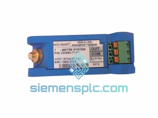
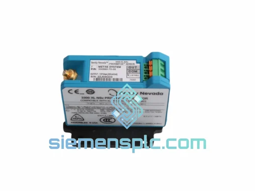
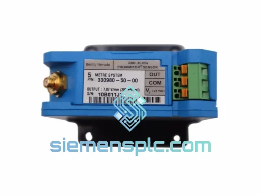
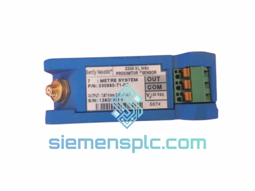
Bently Nevada 330980-71-05 NSV Proximitor Sensor
3309
Origin US
Proximitor Sensor
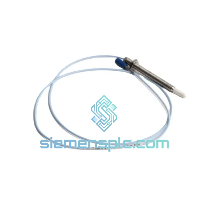
Request verified availability, condition, replacement risk review, packing options and courier lead time for 330905-00-09-10-02-05.
Click Request Quote and the part number is inserted into the inquiry form automatically.
Core fields for model confirmation and RFQ routing. Detailed product narrative remains below.
Your turbine tripped. The DCS is throwing a gap voltage out-of-range alarm. Maintenance is standing by. The OEM says 6–8 weeks lead time. You don’t have 6–8 weeks — you have a production line hemorrhaging revenue by the hour. That’s exactly the scenario the Bently Nevada 330905-00-09-10-02-05 was built for, and it’s exactly why we stock it.
This is a factory-configured, complete proximity transducer system — probe, extension cable, and proximitor matched as a calibrated set. No field calibration. No guesswork. Pull the failed unit, install this one, verify gap voltage, and get your machine back online. We ship from Xiamen within 24 hours of order confirmation via DHL Express or FedEx International Priority.
⚡ URGENT REQUIREMENT? Contact: [email protected] | WhatsApp: +86 18359268345
| Parameter | Specification |
|---|---|
| Part Number | 330905-00-09-10-02-05 |
| Brand | Bently Nevada (Baker Hughes) |
| Series | 3300 XL Proximity Transducer System |
| Sensing Technology | Eddy-Current (Non-Contact) |
| Probe Tip Diameter | 8 mm |
| Linear Measurement Range | 0.25 mm – 2.26 mm (10–90 mil) |
| Output Signal | −18 VDC nominal |
| Scale Factor | 7.87 V/mm (200 mV/mil) |
| Frequency Response | DC to 10,000 Hz |
| Probe Operating Temp. | −35°C to +121°C |
| Proximitor Operating Temp. | −35°C to +85°C |
| Supply Voltage | −24 VDC nominal |
| Target Material (Calibrated) | AISI 4140 Steel |
| Compliance | API 670, CE, RoHS |
| Connector | Standard Bently Nevada Coaxial |
| Probe Body Length Code | 09 (9 mm) |
| Extension Cable Length Code | 10 (~3 m / 10 ft) |
| Availability | ✅ Ready to Ship — Xiamen Stock |
The three failure modes you’ll actually see in the field:
1. Gap Voltage Drift / Out-of-Range Alarm
This is the most common call-out. The monitor card is reading a DC gap voltage outside the −10 V to −18 V window. Before condemning the transducer system, check the proximitor supply voltage first — a sagging −24 VDC rail (anything above −22 V) will shift your gap output and trigger false alarms. If supply is solid, measure gap voltage directly at the proximitor output terminals with a calibrated DMM. If the reading doesn’t match the monitor display, suspect the field wiring or the monitor input card, not the transducer. If gap voltage is genuinely out of range with correct supply, the probe or proximitor has failed.
2. Intermittent Vibration Spikes / Noise Floor Elevation
High-frequency noise injected into the proximity signal is almost always a cable issue — cracked jacket, compromised shield continuity, or a loose coaxial connector at the probe or proximitor end. The 330905-00-09-10-02-05 uses a matched cable length (code 10 = ~3 m). Substituting a different cable length without recalibrating the proximitor will shift the scale factor and introduce measurement error. Always replace the complete matched set.
3. Proximitor Oscillator Failure (No Output / Constant −24 V Output)
A proximitor stuck at supply rail voltage (−24 V) with no probe connected indicates the internal oscillator circuit has failed — typically from sustained overvoltage on the supply rail or moisture ingress into the housing. A proximitor outputting 0 V with probe connected and correct supply usually means the probe coil is open-circuit (physical damage or corrosion at the probe tip). In both cases, the matched system must be replaced as a unit to maintain calibration integrity.
Replacement Procedure — Field Checklist:
Configuration Note: The 3300 XL system does not require DIP switch configuration or firmware matching at the transducer level — the proximitor is a passive analog device. However, verify that the 3300 series monitor input card is configured for the correct transducer type (8 mm, 200 mV/mil scale factor) in the rack configuration software before commissioning.
Proximity transducer systems fail in predictable ways when the environment fights back. The 330905-00-09-10-02-05 is engineered to hold its calibration and signal integrity across the conditions that destroy lesser sensors.
Vibration: The probe body is machined from stainless steel with a ceramic-filled epoxy tip — there is no moving part to fatigue. The coaxial cable assembly uses a braided shield with strain relief at both termination points. In high-vibration installations (compressor bearing housings, gearbox casings), the cable routing and clamping practice matters more than the sensor itself. Use anti-vibration cable clamps at 300 mm intervals and avoid routing adjacent to high-current motor cables.
High Temperature: The probe is rated to +121°C continuous — adequate for most steam turbine bearing housings. For applications approaching this limit (exhaust-end bearings on back-pressure turbines), verify that the extension cable routing keeps the cable body below +85°C. The proximitor housing must remain below +85°C; mount it in a ventilated junction box away from radiant heat sources.
Moisture and Condensation: The proximitor housing carries an IP rating suitable for industrial junction box installation, but it is not designed for direct water exposure. In humid tropical environments or outdoor installations, use a sealed junction box with desiccant packs and inspect the coaxial connector O-rings annually. Moisture at the coaxial connector interface is the leading cause of premature proximitor failure in coastal and offshore installations.
EMI/RFI: The eddy-current signal operates at high frequency (typically 1–2 MHz carrier), making it inherently susceptible to conducted and radiated interference. The braided shield in the extension cable provides the primary defense. Ensure the shield is grounded at one end only (proximitor end) to avoid ground loop currents that appear as low-frequency noise on the vibration signal.
We operate from Xiamen, China — one of the most logistics-efficient export hubs on the mainland, with direct DHL and FedEx gateway access. Here’s what the fulfillment timeline actually looks like:
Day 0 — Order Confirmation: Payment confirmed before 14:00 CST triggers same-day picking and inspection. The unit is photographed, serial number recorded, and packed in anti-static foam with a printed packing list and certificate of conformance.
Day 1 — Export Clearance & Handover: Shipment is tendered to DHL Express or FedEx International Priority with HS code pre-declared (typically 9031.80 for electronic measuring instruments). Commercial invoice and packing list are prepared in English for customs clearance at destination.
Day 2–4 — In Transit: DHL Express from Xiamen reaches most destinations in Southeast Asia within 2 days, Europe and North America within 3–4 days. FedEx International Priority offers comparable transit times with real-time tracking.
Destination Customs: We declare accurate commercial values and correct HS codes on all shipments. For customers in the EU, we can provide EORI-compatible documentation. For customers in the Middle East and Southeast Asia, we have experience with country-specific import requirements and can advise on documentation needs.
For genuine emergency situations — plant shutdown, safety system bypass, regulatory deadline — contact us directly via WhatsApp for real-time stock confirmation and expedited processing. We have fulfilled same-day dispatch requests for customers facing critical downtime situations.
📧 Email: [email protected]
💬 WhatsApp: +86 18359268345
🌐 Web: siemensplc.com
© 2026 siemensplc.com. All rights reserved.
We check the full part number, brand, series and visible nameplate information before quotation.
Sales confirms stock path, condition option, quantity and realistic lead time for export dispatch.
DHL, FedEx, UPS or buyer courier arrangements can be reviewed with packing requirements.
Similar brand or category products for fast comparison and multi-item RFQ lists.