FOXBORO
RFQ Ready
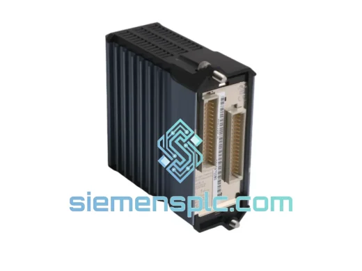
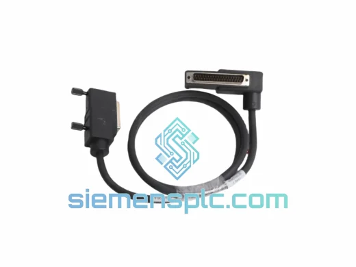
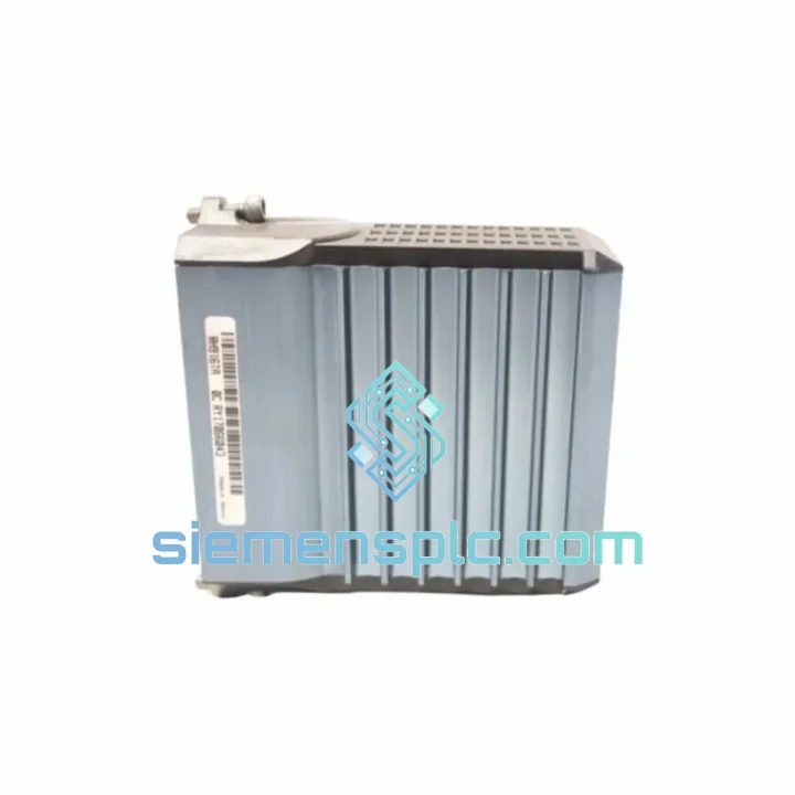
FOXBORO RH916DB DCS Termination Cable – I/A Series
I/A Series
Origin FR
DCS Termination Cable
Request verified availability, condition, replacement risk review, packing options and courier lead time for FBM242 RH916TA.
Click Request Quote and the part number is inserted into the inquiry form automatically.
Core fields for model confirmation and RFQ routing. Detailed product narrative remains below.
The FOXBORO FBM242 RH916TA is a dedicated interface module within the Foxboro I/A Series Distributed Control System (DCS) platform, engineered to serve as a structured communication bridge between field instrumentation and the system’s Field Control Processor (FCP). Unlike general-purpose I/O modules, the FBM242 is purpose-built to handle protocol-level interfacing, enabling deterministic data exchange across the Nodebus backplane while maintaining electrical isolation from field-side signal sources.
In a typical I/A Series control loop, the FBM242 occupies the interface tier between the FCP270 or FCP280 processor and the physical field device layer. Its primary function is to translate field-level signals — whether analog, discrete, or serial — into structured data packets that the FCP can process within its real-time scan cycle. The module’s hardware architecture is designed around a dual-port memory model: one port synchronized to the Nodebus clock domain, the other aligned to the field-side polling cycle. This eliminates the need for software-level handshaking and reduces latency jitter to sub-millisecond levels under normal operating conditions.
The RH916TA revision designation indicates a specific hardware build state, including PCB revision, firmware baseline, and component-level changes relative to earlier FBM242 variants. Procurement teams and system integrators should verify the revision code against their existing FCP firmware version to confirm compatibility, particularly in installations running Foxboro Evo or legacy I/A Series v8.x software stacks.
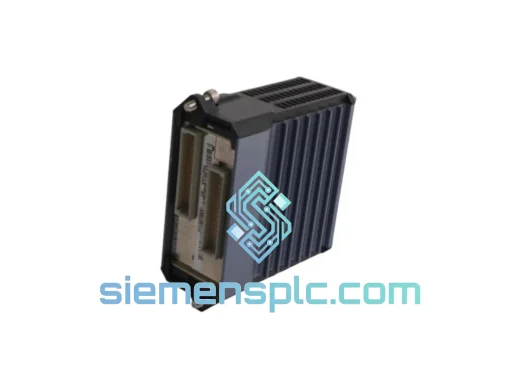
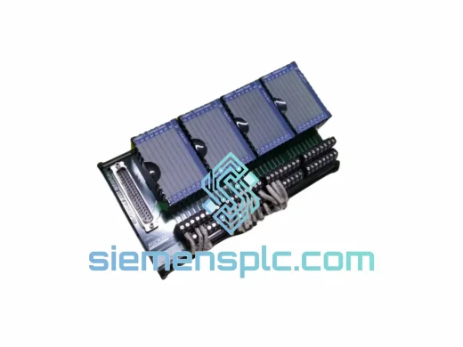
From a physical standpoint, the FBM242 RH916TA mounts directly into the FBM carrier assembly, drawing power from the carrier’s regulated 24 VDC bus. The module does not require external power conditioning, and its onboard DC-DC converter provides galvanic isolation between the carrier bus and the field-side circuitry. This isolation architecture is critical in process environments where ground loops, common-mode noise, or high-voltage transients from field cabling could otherwise corrupt signal integrity or damage backplane components.
The module’s EMC design follows IEC 61000-4 series test criteria, with particular attention to conducted immunity (IEC 61000-4-6) and fast transient burst immunity (IEC 61000-4-4). Internal signal routing uses differential pair traces with controlled impedance, and the PCB stack-up incorporates dedicated ground planes to suppress radiated emissions. In high-noise environments — such as those adjacent to variable frequency drives, large motor starters, or high-current bus bars — the FBM242’s shielding architecture provides measurable attenuation of coupled interference without requiring additional external filtering hardware.
Diagnostics are handled through the module’s self-test firmware, which executes a memory integrity check, communication path verification, and field-side continuity test at each power-on cycle. Fault states are reported back to the FCP via the Nodebus status word, allowing the control system’s alarm management layer to generate actionable alerts without operator intervention at the module level. This diagnostic transparency is a key operational advantage in unmanned or remotely monitored process facilities.
Real-time Stock & RFQ: [email protected] | WhatsApp: +86 18359268345
| Parameter | Specification |
|---|---|
| Manufacturer | FOXBORO (Schneider Electric) |
| Part Number | FBM242 |
| Revision / Build State | RH916TA |
| Module Classification | Interface Module – Fieldbus I/O Bridge |
| Compatible Platform | Foxboro I/A Series DCS; Foxboro Evo |
| Compatible Processors | FCP270, FCP280 |
| Carrier Bus Voltage | 24 VDC (from FBM carrier assembly) |
| Field-Side Isolation | Galvanic (DC-DC converter, optocoupler barrier) |
| Communication Interface | Nodebus (proprietary Foxboro backplane protocol) |
| EMC Immunity Standard | IEC 61000-4-4 (EFT/Burst), IEC 61000-4-6 (Conducted) |
| Operating Temperature | 0 °C to +60 °C (module ambient) |
| Storage Temperature | -40 °C to +85 °C |
| Relative Humidity | 5% to 95% non-condensing |
| Module Weight | Approx. 200 g |
| Mounting | FBM carrier rail (snap-fit, tool-free) |
| Diagnostic Reporting | Nodebus status word; power-on self-test (POST) |
| Warranty | 12 months from date of shipment |
The FBM242 RH916TA’s internal architecture is structured around three functional blocks: the Nodebus interface logic, the field-side signal conditioning stage, and the isolation barrier. Understanding how these blocks interact explains the module’s reliability profile in demanding process environments.
Nodebus Interface Logic: The Nodebus is a deterministic, token-passing backplane protocol operating at a fixed clock rate. The FBM242’s Nodebus interface block contains a dedicated ASIC that handles token acquisition, data framing, and CRC generation without CPU intervention. This hardware-offload approach ensures that backplane communication latency remains constant regardless of field-side signal activity, which is essential for maintaining scan cycle determinism in the FCP.
Dual-Port Memory Architecture: Data exchange between the Nodebus domain and the field-side polling domain occurs through a dual-port SRAM block. Each port operates independently on its own clock domain, with hardware arbitration logic managing simultaneous access conflicts. This eliminates software semaphore overhead and ensures that a field-side polling delay cannot propagate into the Nodebus scan cycle — a common failure mode in modules that use shared-bus memory architectures.
Optocoupler Isolation Barrier: The field-side isolation uses high-speed optocouplers rated for common-mode transient immunity (CMTI) exceeding 10 kV/µs. This specification is relevant in installations where field cabling runs parallel to power conductors or through areas with significant ground potential differences. The optocoupler barrier prevents transient energy from coupling into the backplane, protecting both the FBM242 and adjacent modules in the carrier assembly.
EMC Ground Plane Design: The PCB uses a four-layer stack-up with dedicated power and ground planes on the inner layers. Signal traces on the outer layers are routed with controlled impedance (50 Ω differential pairs for high-speed signals), and the ground planes provide a low-impedance return path that suppresses both conducted and radiated emissions. Ferrite beads on the power supply inputs attenuate high-frequency noise from the carrier bus before it reaches the module’s internal regulators.
Power-On Self-Test (POST) Firmware: At each power cycle, the module’s embedded firmware executes a structured POST sequence: SRAM integrity check (walking-ones pattern), Nodebus loopback verification, and field-side continuity test. Any failure in this sequence sets a fault bit in the Nodebus status word, which the FCP reads and escalates to the alarm management system. This design means that a failed module is detected within seconds of power application, rather than being discovered during a process upset.
Every FOXBORO FBM242 RH916TA unit supplied by siemensplc.com is sourced as genuine OEM hardware. Each module undergoes a structured incoming inspection covering label authenticity, PCB condition, connector pin integrity, and revision code verification against the order specification. Units that do not pass inspection are quarantined and not offered for sale.
Shipments originate from our warehouse in Xiamen, China, a major logistics hub with direct access to international express carriers including DHL Express, FedEx International Priority, and UPS Worldwide Expedited. In-stock units are typically dispatched within 1–2 business days of order confirmation. For urgent plant maintenance requirements, same-day dispatch is available on request for orders confirmed before 14:00 CST.
All export documentation — commercial invoice, packing list, and HS code declaration — is prepared in compliance with Chinese customs regulations and the import requirements of the destination country. For buyers in the EU, Middle East, Southeast Asia, and the Americas, we have established logistics lanes with documented transit time benchmarks. Bulk orders can be consolidated for sea freight dispatch with full container load (FCL) or less-than-container load (LCL) options.
A 12-month warranty applies to all units from the date of shipment. Warranty coverage addresses functional failure under normal operating conditions and includes return material authorization (RMA) processing with replacement dispatch within 5 business days of confirmed fault diagnosis.
Email: [email protected]
WhatsApp: +86 18359268345
Web: siemensplc.com
Location: Xiamen, China
© 2026 siemensplc.com. All rights reserved.
We check the full part number, brand, series and visible nameplate information before quotation.
Sales confirms stock path, condition option, quantity and realistic lead time for export dispatch.
DHL, FedEx, UPS or buyer courier arrangements can be reviewed with packing requirements.
Similar brand or category products for fast comparison and multi-item RFQ lists.