FUJI
RFQ Ready
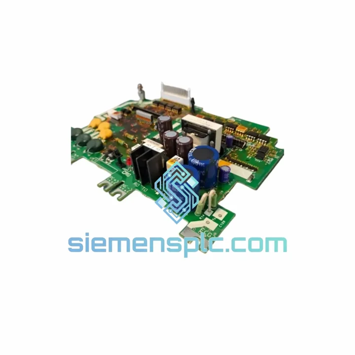
FUJI SA531121-02 E11-C4PCB Inverter Drive Board
Origin Not specified
Inverter Drive Board
Request verified availability, condition, replacement risk review, packing options and courier lead time for G11-PPCB-4-2.
Click Request Quote and the part number is inserted into the inquiry form automatically.
Core fields for model confirmation and RFQ routing. Detailed product narrative remains below.
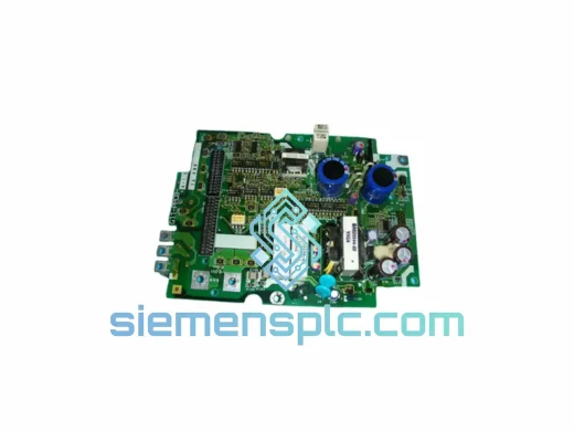
The FUJI G11-PPCB-4-2.2 (Assembly No. SA528530-05) is the OEM-designated Power Printed Circuit Board (PPCB) for the FUJI FRENIC G11 series variable frequency drive platform, specifically engineered for the 2.2 kW, 400V three-phase voltage class. Within the drive’s internal architecture, this board occupies the critical interface layer between the DC bus capacitor bank and the IGBT power module stack. It carries gate trigger signals from the control board to the IGBT bridge, manages bootstrap power supply rails for the high-side gate drivers, and provides the isolated feedback paths that allow the main CPU to monitor DC bus voltage and phase current in real time.
Unlike generic aftermarket boards, the SA528530-05 assembly is manufactured to FUJI Electric’s original Gerber specifications, using the same substrate material (FR-4, 1.6 mm, 2 oz copper pour), the same gate resistor values, and the same optocoupler part numbers as the factory-fitted board. This matters because even a 10% deviation in gate resistance alters IGBT switching transients, directly affecting EMI signature and thermal dissipation at the module junction. Substituting non-OEM boards in this position is a documented root cause of premature IGBT failure in field service reports.
The G11 series was designed for continuous-duty industrial applications where drive availability is a process constraint, not a convenience. Replacing a failed PPCB at board level — rather than swapping the entire drive chassis — reduces material cost by 60–80% and cuts mean-time-to-repair (MTTR) from days to hours, provided the correct OEM board is available on the shelf.
Real-time Stock & RFQ: [email protected] | WhatsApp: +86 18359268345
| Parameter | Value |
|---|---|
| Part Number | G11-PPCB-4-2.2 |
| Assembly Number | SA528530-05 |
| Compatible Drive Series | FUJI FRENIC G11 (FRN2.2G11S-4EN and equivalent 2.2 kW / 400V variants) |
| Board Function | Power PCB — IGBT gate drive, DC bus interface, bootstrap supply |
| Voltage Class | 400V AC (3-phase input) |
| DC Bus Operating Range | Approx. 530–620 V DC (nominal 565 V DC at 400V AC input) |
| Power Rating | 2.2 kW |
| Gate Drive Output Voltage | +15V / −8V (typical IGBT gate drive levels per FUJI G11 design) |
| Isolation Barrier | Optocoupler-based galvanic isolation between control logic and power stage |
| PCB Substrate | FR-4, 1.6 mm, 2 oz copper |
| Connector Interface | OEM direct plug-in, no adapter required |
| Operating Temperature | −10°C to +50°C (ambient, per G11 drive enclosure spec) |
| Storage Temperature | −25°C to +65°C |
| Humidity | 5–95% RH, non-condensing |
| Weight (board only) | Approx. 180–220 g |
| Condition | New / Surplus New — OEM original |
| Warranty | 12 months from date of dispatch |
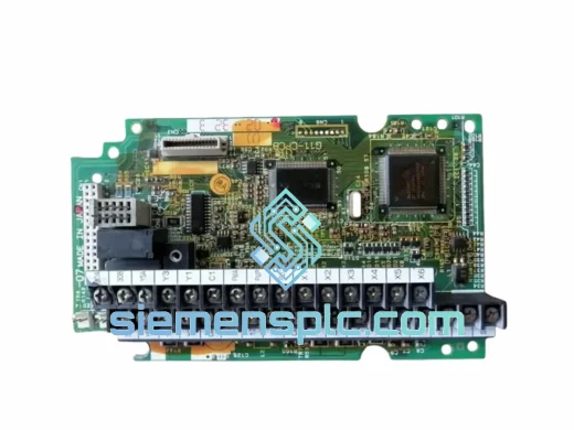
The PPCB in a FUJI G11 drive performs three distinct hardware functions that are tightly coupled in the SA528530-05 layout:
1. IGBT Gate Drive Circuit: Each of the six IGBT switches in the three-phase bridge requires an isolated gate drive channel. The SA528530-05 implements these using high-speed optocouplers (HCPL-316J class or equivalent) that provide both signal isolation and fault feedback. The gate drive output swings between +15V (turn-on) and −8V (turn-off), with the negative bias being essential to prevent parasitic turn-on under high dV/dt conditions on the DC bus — a failure mode that causes shoot-through and immediate IGBT destruction. The gate resistors on this board are precision-matched to the 2.2 kW IGBT module’s input capacitance, controlling the switching speed to balance switching loss against EMI generation.
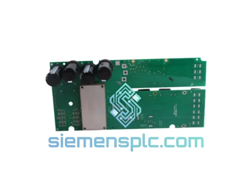
2. Bootstrap Power Supply: The high-side gate drivers for the upper IGBT switches require a floating power supply referenced to each phase output node. The SA528530-05 implements bootstrap capacitor charging circuits that replenish the high-side supply during each PWM cycle. The bootstrap capacitor values and charge resistor sizing are optimized for the G11’s carrier frequency range (typically 0.75–15 kHz), ensuring adequate gate drive energy even at low modulation depths where bootstrap refresh intervals are longest.
3. EMC Design and Isolation Architecture: The board layout enforces a strict separation between the high-voltage power plane (DC bus traces, gate drive outputs) and the low-voltage signal plane (optocoupler inputs, feedback signals). Creepage and clearance distances on the SA528530-05 are designed to IEC 60664-1 requirements for 400V class equipment, providing a minimum 8 mm creepage across the isolation barrier. Ferrite beads are placed on gate drive output traces to suppress high-frequency ringing that would otherwise couple into adjacent signal traces and generate false fault triggers on the control board.
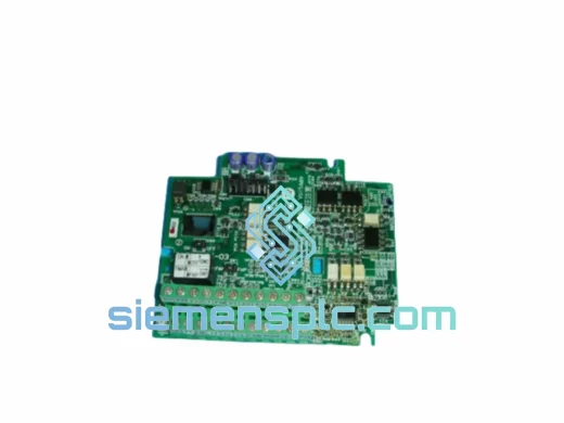
4. DC Bus Voltage Sensing: A resistor divider network on the PPCB scales the DC bus voltage down to a signal-level analog output that feeds the main control CPU. This path includes a low-pass RC filter to reject PWM switching noise, ensuring the CPU receives a clean DC bus reading for overvoltage and undervoltage protection logic. The divider ratio is factory-calibrated; substituting non-OEM boards with incorrect divider values will cause the drive to report false DC bus faults or, more dangerously, fail to trip on genuine overvoltage events.
Every G11-PPCB-4-2.2 SA528530-05 unit dispatched from our Xiamen, China facility is sourced from verified FUJI Electric authorized distribution channels or traceable surplus inventory with documented provenance. Prior to dispatch, each board undergoes visual inspection for solder joint integrity, component presence verification against the OEM BOM, and ESD handling compliance throughout the receiving and storage process.
Units are packaged in anti-static ESD bags with foam cushioning inside double-wall corrugated cartons, meeting ISTA 2A transit test requirements for fragile electronic assemblies. Lot traceability documentation is available upon request for customers operating under ISO 9001 or IEC 62443 quality management frameworks.
From Xiamen, we ship via DHL Express, FedEx International Priority, and UCP air freight, with typical transit times of 3–5 business days to Europe, 4–6 days to North America, and 2–3 days to Southeast Asia. Export documentation including commercial invoice, packing list, and HS code declaration (HS 8537.10) is prepared for all international shipments. All units carry a 12-month warranty covering manufacturing defects and are eligible for advance replacement under our RMA program for qualified accounts.
Email: [email protected]
WhatsApp: +86 18359268345
Web: siemensplc.com
Location: Xiamen, China
© 2026 siemensplc.com. All rights reserved.
We check the full part number, brand, series and visible nameplate information before quotation.
Sales confirms stock path, condition option, quantity and realistic lead time for export dispatch.
DHL, FedEx, UPS or buyer courier arrangements can be reviewed with packing requirements.
Similar brand or category products for fast comparison and multi-item RFQ lists.