GE
RFQ Ready
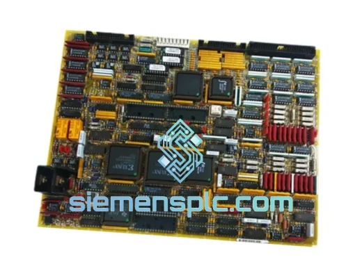
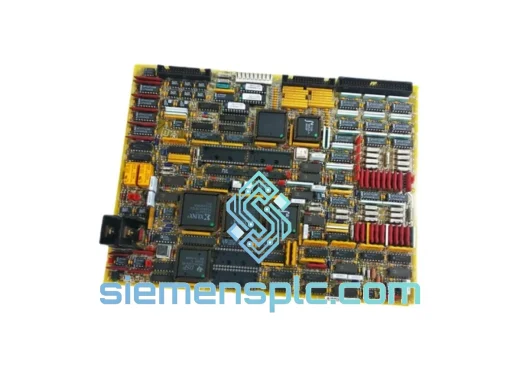
GE DS200TCQCG1BKG Turbine Control Module – Mark V Series
Mark V
Origin US
Turbine Control Module
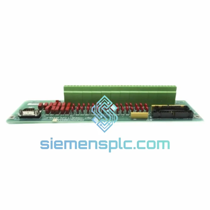
Request verified availability, condition, replacement risk review, packing options and courier lead time for DS200QTBAG1ACB.
Click Request Quote and the part number is inserted into the inquiry form automatically.
Core fields for model confirmation and RFQ routing. Detailed product narrative remains below.
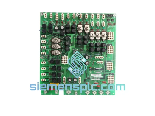
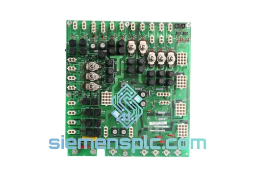
The DS200QTBAG1ACB is a passive field termination board produced by General Electric for deployment within the Mark V turbine control platform. Its function is structurally defined: it establishes the electrical boundary between plant-floor field wiring and the Mark V controller card set. Every analog measurement and discrete state that the control system processes passes through this boundary. In Mark V Triple Modular Redundant (TMR) configurations, three independent controller paths each reference field signals through dedicated termination interfaces. Any impedance asymmetry or contact degradation at this layer introduces differential signal offsets that the TMR voting logic cannot attribute to a specific source — the result is either spurious protective trips or masked fault conditions, both of which carry direct operational and safety consequences.
The DS200 board family was designed to operate continuously within the thermal and mechanical environment of gas turbine enclosures. Ambient temperatures cycle from near 0°C at cold start to sustained values approaching 60°C during full-load operation. Relative humidity can reach 95% non-condensing during weather events or enclosure wash-down. Broadband mechanical vibration from the turbine shaft and auxiliary rotating equipment is transmitted through the panel structure to every mounted component. The DS200QTBAG1ACB addresses these conditions through material selection — multi-layer FR4 substrate, gold-plated edge connector contacts, and conformal-coated PCB surface — rather than through derating or environmental enclosures.
Real-time Stock & RFQ: [email protected] | WhatsApp: +86 18359268345
| Parameter | Specification |
|---|---|
| Part Number | DS200QTBAG1ACB |
| Manufacturer | General Electric (GE) |
| Platform Compatibility | Mark V Turbine Control System (TMR & Simplex) |
| Board Function | Passive Field I/O Signal Termination Interface |
| Form Factor | Rack-mount PCB, Mark V panel-compatible footprint |
| Operating Temperature | 0°C to +60°C continuous |
| Storage Temperature | −40°C to +85°C |
| Humidity Tolerance | 5% to 95% RH, non-condensing |
| Supported Signal Classes | 4–20 mA analog, 0–10 VDC analog, 24 VDC discrete I/O |
| Field Wiring Termination | Screw-clamp terminal blocks, 0.5–2.5 mm² (AWG 20–14) |
| Backplane Interface | Gold-plated edge connector, Mark V card cage specification |
| PCB Construction | Multi-layer FR4, IPC Class 2 assembly, conformal coated (IPC-CC-830) |
| Transient Protection | TVS diode arrays per channel, IEC 61000-4-5 Level 2 |
| EFT Immunity | RC filter networks, IEC 61000-4-4 Level 3 |
| Common-Mode Rejection | >80 dB at 50/60 Hz (analog input channels) |
| Channel Isolation Resistance | >100 MΩ at 500 VDC between adjacent channels |
| Contact Resistance | <10 mΩ (gold-plated edge connector, full operating envelope) |
| Country of Origin | United States |
| Warranty | 12 months from shipment date |
The DS200QTBAG1ACB performs three architecturally distinct functions at the physical layer: signal routing, passive conditioning, and EMC boundary enforcement. These are often described as a single termination function in generic documentation, but their separation is essential to understanding why board-level failures produce specific, reproducible fault signatures in the Mark V diagnostic log.
Signal Routing Layer: Field conductors from thermocouples, RTDs, 4–20 mA transmitters, and 24 VDC discrete devices land on screw-clamp terminal blocks. Internal PCB traces route each signal pair from the terminal block to the corresponding pin on the backplane edge connector. Trace width and copper weight are selected to control impedance across the operating temperature range, where FR4 dielectric properties shift measurably between 0°C and 60°C. Uncontrolled trace impedance at this scale introduces differential offsets between the three TMR paths that accumulate over thermal cycles and eventually exceed the voting algorithm’s tolerance window.
Passive Conditioning Network: Each analog channel incorporates a series current-limiting resistor, a differential-mode RC low-pass filter, and a bidirectional TVS diode pair. The RC filter cutoff is positioned above the process signal bandwidth — typically below 10 Hz for turbine control loops — but below the switching frequencies of variable-frequency drives in the 2–16 kHz range. This placement attenuates VFD-induced common-mode noise by a minimum of 40 dB at 5 kHz without introducing phase lag that would affect closed-loop stability. The TVS diode pair clamps inductive switching transients from solenoid valves, relay coils, and motor contactors to safe voltage levels at the field terminal entry point, protecting I/O card input circuitry without requiring external surge protection devices in the field conduit.
EMC Boundary Architecture: The board’s ground plane is segmented to isolate the field-side reference from the controller-side reference, with a single controlled crossing point that prevents ground loop formation. Field cable shields terminate to the field-side ground plane through low-inductance connections, diverting shield currents — which can reach tens of milliamps in multi-grounded industrial environments — to the panel earth rather than through signal return conductors. This architecture sustains common-mode rejection above 80 dB at 50/60 Hz for analog input channels, a requirement for accurate measurement of thermocouple signals in the millivolt range in the presence of power-frequency interference from adjacent motor drives and transformer feeders.
Gold-plated edge connector contacts maintain contact resistance below 10 mΩ across the full temperature and vibration envelope. Fretting corrosion — progressive oxidation of contact surfaces caused by micro-motion under vibration — is the primary long-term failure mechanism for tin-plated contacts in rotating machinery environments. Gold plating eliminates this mechanism by providing a noble metal surface that does not form resistive oxide layers, preserving signal integrity across the board’s service life without periodic connector maintenance.
Each DS200QTBAG1ACB unit processed through our Xiamen facility undergoes a four-stage verification protocol before dispatch. The first stage is a physical inspection covering PCB surface condition, solder joint integrity under 10× magnification, connector pin geometry, and conformal coating coverage across all component bodies and exposed trace areas. The second stage is passive component verification using precision LCR measurement to confirm that resistor and capacitor values fall within the original GE tolerance band — a step that identifies counterfeit components whose markings are correct but whose electrical values deviate from specification. The third stage is a continuity and isolation check across all signal paths, verifying that no open circuits exist in routing traces and that isolation resistance between adjacent channels exceeds 100 MΩ at 500 VDC. The fourth stage is part number authentication, cross-referencing silk-screen markings, PCB revision codes, and component date codes against GE OEM documentation records.
Units are packaged in IEC 61340-compliant anti-static bags with humidity indicator cards, cushioned within closed-cell polyethylene foam inserts, and enclosed in double-wall corrugated export cartons with corner reinforcement. Shipments are dispatched via DHL Express, FedEx International Priority, or UPS Worldwide Express from Xiamen Gaoqi International Airport. Transit times are 3 to 5 business days to industrial procurement centers in Western Europe, the Gulf Cooperation Council states, Southeast Asia, and North America. Complete export documentation — commercial invoice, packing list, certificate of origin, and material safety data sheet where applicable — accompanies every shipment to support customs clearance without delay at destination ports. The 12-month warranty covers defects in materials and workmanship from the shipment date, with replacement units dispatched on priority freight to minimize plant downtime exposure.
Email: [email protected]
WhatsApp: +86 18359268345
Web: siemensplc.com
Location: Xiamen, China
© 2026 siemensplc.com. All rights reserved.
We check the full part number, brand, series and visible nameplate information before quotation.
Sales confirms stock path, condition option, quantity and realistic lead time for export dispatch.
DHL, FedEx, UPS or buyer courier arrangements can be reviewed with packing requirements.
Similar brand or category products for fast comparison and multi-item RFQ lists.