GE
In Stock OK
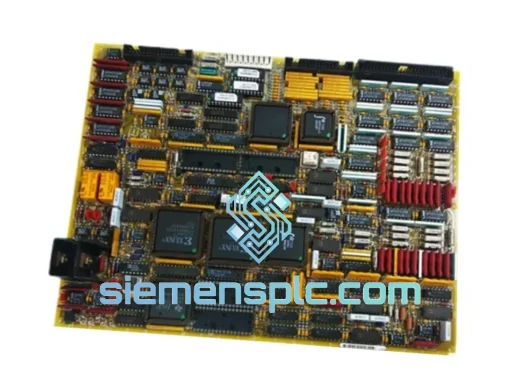
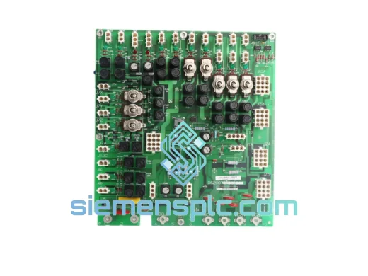
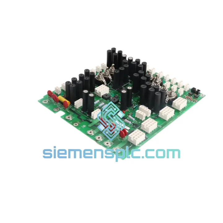
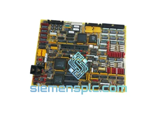
GE DS200TCDAG1ADA Digital I/O Board – Mark V Turbine Control
Request verified availability, condition, replacement risk review, packing options and courier lead time for DS200TCDAG1ADA.
BrandGE
Part NumberDS200TCDAG1ADA
ConditionAvailability Check
Lead TimeRFQ Confirmation
DocumentsDatasheet / photos by RFQ
ShippingExport packing available
Auto-filled RFQ
DS200TCDAG1ADA
Click Request Quote and the part number is inserted into the inquiry form automatically.
- Reply by email: [email protected]
- WhatsApp / Tel: +86 18359268345
- Mon-Sat 9:00-18:00 GMT+8
Procurement Data
Key Product Information
Core fields for model confirmation and RFQ routing. Detailed product narrative remains below.
- Brand
- GE
- Primary Part Number
- DS200TCDAG1ADA
- Product Type
- Digital I/O Board
- Series / Family
- Mark V
- Manufacturer
- General Electric (GE)
- Country of Origin
- US
- Catalog Category
- I/O Modules
- Operating Temp.
- 0 °C to +60 °C ambient (standard enclosed panel)
- Warranty
- 12 months against defects in materials and workmanship
Model confirmed for inquiry
DS200TCDAG1ADA
Send quantity, destination and urgency. The RFQ form keeps this part number attached.
Request Quote
Product Overview
GE DS200TCDAG1ADA — High-Density Digital I/O Interface in Mark V Turbine Control Architecture
The DS200TCDAG1ADA is a discrete digital input/output board designed for deployment within General Electric’s Mark V turbine control system, specifically within the TCDA (Turbine Control Digital/Analog) I/O rack assembly. Its primary function is to serve as the hardwired interface layer between field-level discrete signals — trip contacts, permissive relays, solenoid valve feedback, and limit switches — and the Mark V’s triple-redundant TMR (Triple Modular Redundancy) processing core. In a Mark V panel, the TCDA rack typically houses multiple DS200TCDAG1ADA boards in parallel, each handling a defined block of I/O addresses mapped to the controller’s I/O configuration table. Signal conditioning, isolation, and address decoding are all performed on-board, reducing the processing burden on the TCCA (Turbine Control Communication/Analog) master controller card.
Real-time Stock & RFQ: [email protected] | WhatsApp: +86 18359268345
Technical Parameters
| Part Number | DS200TCDAG1ADA |
| Manufacturer | General Electric (GE) |
| Compatible System | GE Mark V Turbine Control (TCDA Rack) |
| Board Classification | Digital I/O Interface Board |
| Form Factor | Single-slot PCB, TCDA rack-mount format |
| Digital Input Voltage Range | 24 VDC / 125 VDC (field-selectable per channel group) |
| Input Logic Threshold | Typically ≥18 VDC for logic HIGH; ≤6 VDC for logic LOW (24 VDC mode) |
| Output Type | Relay contact outputs (dry contact, normally open/normally closed) and solid-state driver outputs |
| Output Contact Rating | Up to 2 A resistive at 125 VDC / 250 VAC (relay channels) |
| Isolation Architecture | Opto-coupler isolation on all input channels; transformer isolation on backplane power rails |
| Backplane Interface | Parallel data bus to Mark V TCCA/TCDA rack backplane; address-decoded I/O mapping |
| Operating Temperature | 0 °C to +60 °C ambient (standard enclosed panel) |
| Storage Temperature | −40 °C to +85 °C |
| Relative Humidity | 5% to 95% non-condensing |
| Board Weight | 980 g |
| Reference Manual | GEH-5980 (GE Mark V Application Manual) |
| Warranty | 12 months against defects in materials and workmanship |
Hardware Logical Analysis
The DS200TCDAG1ADA’s input stage employs opto-coupler isolation on every discrete input channel. Each opto-coupler presents a high-impedance input to the field wiring loop while galvanically separating the field voltage domain (24 VDC or 125 VDC) from the board’s internal 5 VDC logic domain. This architecture eliminates ground loop currents that would otherwise introduce noise into the Mark V’s signal processing chain — a critical requirement in turbine control panels where high-current motor starters, solenoid valves, and excitation equipment share the same physical enclosure.
On the output side, relay contact outputs use electromechanical relays with bifurcated gold-plated contacts, which maintain reliable continuity at low-current signal levels (as low as 10 mA) while also handling the inrush currents associated with solenoid valve coils. Solid-state driver outputs, where present, use power transistor arrays with flyback diode protection to suppress inductive kickback from relay coil loads — preventing voltage transients from propagating back into the board’s logic circuitry.
The backplane interface uses a parallel address-decoded bus architecture. Each DS200TCDAG1ADA occupies a defined slot address within the TCDA rack, and the Mark V controller reads and writes I/O data via memory-mapped register access across the backplane. This deterministic access model — as opposed to a serialized fieldbus — ensures that I/O scan cycle times remain bounded and predictable, a non-negotiable requirement for turbine trip logic where response latency must be held below defined safety thresholds.
EMC performance is reinforced through board-level design: signal traces are routed with controlled impedance, decoupling capacitors are placed at each IC power pin, and the board ground plane is segmented to prevent high-frequency switching noise from the output drivers from coupling into the input signal conditioning circuitry. The TCDA rack’s sheet-metal enclosure provides additional shielding attenuation against radiated emissions from adjacent variable-frequency drives and excitation transformers common in turbine control rooms.
System Integration Benefits
- Deterministic I/O Scan Latency: The parallel backplane bus architecture delivers bounded I/O read/write cycle times, ensuring that trip permissive logic in the Mark V TMR core receives updated field signal states within each controller scan cycle — typically 10–20 ms for discrete I/O in Mark V configurations.
- TMR Voting Transparency: In a triple-redundant Mark V panel, three DS200TCDAG1ADA boards (one per controller — R, S, T) read the same field signals independently. The TMR voting logic in the TCCA processor compares all three readings; a single board fault does not cause a spurious trip, and the discrepancy is flagged as a diagnostic alarm — preserving both safety and availability.
- Galvanic Field Isolation: Opto-coupler isolation on every input channel prevents field-side ground faults from propagating into the controller logic domain, protecting the Mark V processor from damage and eliminating common-mode noise that would degrade signal integrity on adjacent analog channels.
- Mixed Voltage Field Compatibility: Support for both 24 VDC and 125 VDC input levels within the same board (via jumper or hardware configuration) allows a single board type to interface with both modern low-voltage field devices and legacy 125 VDC plant wiring — reducing spare parts inventory complexity.
- Relay Contact Longevity: Bifurcated gold-plated relay contacts maintain reliable continuity across the full specified load range, from milliamp-level signal circuits to 2 A solenoid valve coil loads, without requiring separate interposing relay panels for low-current applications.
- Diagnostic Register Visibility: The Mark V controller can read board-level diagnostic status registers via the backplane bus, enabling the HMI to display per-channel fault states, output driver overcurrent conditions, and board health indicators — providing maintenance engineers with actionable diagnostic data without physical panel access.
- Direct Rack Replacement: The DS200TCDAG1ADA is a form-fit-function replacement within the TCDA rack. No firmware changes, no I/O configuration table edits, and no recalibration are required for a like-for-like board swap — minimizing turbine outage duration during corrective maintenance.
- Inductive Load Transient Suppression: Flyback diode arrays on solid-state output driver channels clamp inductive kickback from solenoid valve coils and relay coils to safe levels, preventing voltage transients from exceeding the breakdown ratings of the output transistor array and extending mean time between failures (MTBF) for the output stage.
Quality Assurance & Global Logistics
Every DS200TCDAG1ADA unit dispatched from our Xiamen, China facility undergoes a structured pre-shipment process. Visual inspection covers PCB surface condition, component seating, connector pin integrity, and evidence of prior thermal stress or moisture ingress. Functional bench verification confirms power-on stability and I/O channel continuity using GE-compatible test configurations. Each unit is serialized, condition-graded, and logged in our traceability database prior to packaging.
Packaging uses multi-layer ESD protection: anti-static inner bag, foam-cushioned rigid outer carton, and moisture barrier desiccant pack — ensuring the board arrives in the same condition it left our facility regardless of transit duration or handling conditions. From Xiamen, we ship via DHL Express, FedEx International Priority, and UPS Worldwide Expedited, with typical transit times of 3–5 business days to Europe, North America, the Middle East, and Southeast Asia. Emergency outage shipments can be dispatched same-day for orders confirmed before 14:00 CST. All units carry a 12-month warranty against defects in materials and workmanship from the date of shipment.
Contact Information
Email: [email protected]
WhatsApp: +86 18359268345
Web: siemensplc.com
Location: Xiamen, China
© 2026 siemensplc.com. All rights reserved.
Ready to quote
[email protected]
Send This Part Number to Sales
RFQ workflow
Quality workflow ->
Confirmation Process
01Model confirmation
We check the full part number, brand, series and visible nameplate information before quotation.
02Availability reply
Sales confirms stock path, condition option, quantity and realistic lead time for export dispatch.
03Packing & courier
DHL, FedEx, UPS or buyer courier arrangements can be reviewed with packing requirements.
Continue sourcing
Browse full catalog ->
Related Automation Parts
Similar brand or category products for fast comparison and multi-item RFQ lists.
GE
RFQ Ready
GE DS200TCQCG1BKG Turbine Control Module – Mark V Series
Mark V
Origin US
Turbine Control Module
GE
RFQ Ready
GE DS200TCQBG1BCB DS215TCQBG1BZZ01A Analog I/O Board
Mark V
Origin US
PLC / DCS I/O Module