GE
RFQ Ready
GE IS210MVRBH1A I/O Interface Board – Mark VIe Series
Mark VI
Origin US
I/O Interface Board
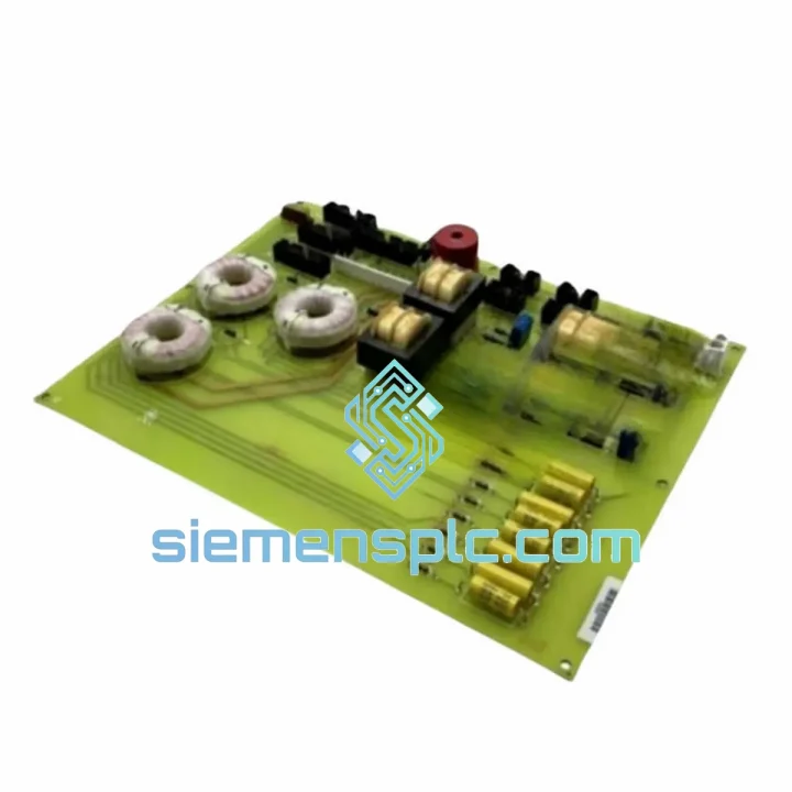
Request verified availability, condition, replacement risk review, packing options and courier lead time for DS200TCEBG1AAB.
Click Request Quote and the part number is inserted into the inquiry form automatically.
Core fields for model confirmation and RFQ routing. Detailed product narrative remains below.
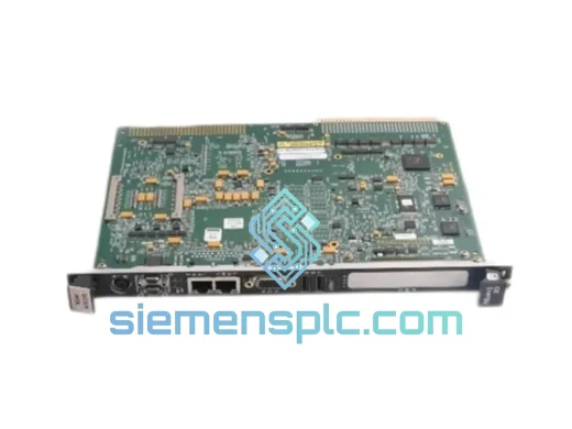
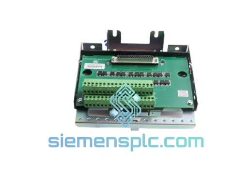
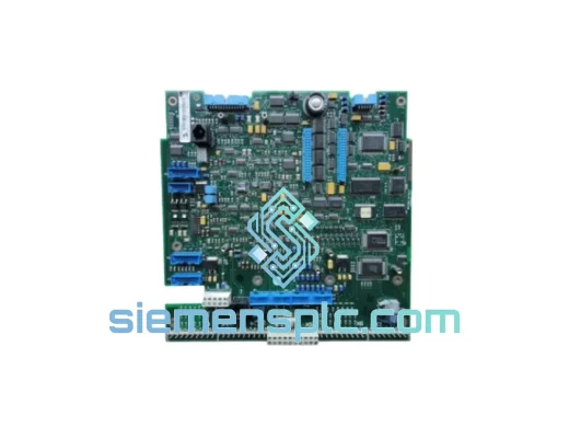
The DS200TCEBG1AAB is a discrete relay output board designed for integration within General Electric’s Mark VI Turbine Control System. The Mark VI platform governs protective, sequencing, and actuation logic across gas turbine, steam turbine, and combined-cycle power generation assets. Within this architecture, the relay output board functions as the terminal actuation interface between the controller’s voted digital logic and hardwired field devices — including trip solenoids, motor contactors, annunciator relays, and permissive interlock circuits. Loss of a relay output board in a live control loop does not produce a soft degradation; it eliminates an actuation path, which in a Triple Modular Redundant (TMR) configuration forces a channel mismatch condition and, depending on the voted output assignment, may initiate a protective shutdown sequence.
The DS200TCEBG1AAB belongs to the TCEB board family within the DS200 I/O series. These boards interface with the Mark VI’s VCMI (VME Communication and Memory Interface) backplane via JR1/JR2 edge connectors. The relay contacts are rated for dry-contact switching of control-voltage field circuits — typically 24 VDC or 120 VAC — with per-channel optical isolation that prevents ground-loop currents from the field wiring harness from coupling into the controller’s logic ground plane. Each output channel is individually fused at the board level; fuse status is polled in real time by GE’s ToolboxST engineering workstation, allowing maintenance personnel to identify a blown output fuse without physical board extraction or loop interruption.
The board’s relay contacts use gold-flashed silver-alloy construction. This material selection addresses a specific failure mode in low-energy dry-contact circuits: pure silver contacts develop silver oxide films under low-current switching conditions, increasing contact resistance above the 1 Ω threshold that many 24 VDC PLC input modules cannot tolerate. The gold flash layer prevents oxide formation during storage and low-frequency switching intervals, maintaining contact resistance below 100 mΩ across the rated service life of the relay mechanism.
In turbine control applications, the DS200TCEBG1AAB handles output assignments that include fuel valve trip solenoids, lube oil pump contactors, generator breaker trip coils, and flame detector relay drivers. Each of these loads presents a different electrical characteristic — inductive, resistive, or capacitive — and the board’s output circuit design accommodates the full range without requiring external snubber networks for standard field device types.
Real-time Stock & RFQ: [email protected] | WhatsApp: +86 18359268345
| Parameter | Specification |
|---|---|
| Part Number | DS200TCEBG1AAB |
| Manufacturer | General Electric (GE) |
| Product Family | DS200 TCEB — Mark VI Turbine Control I/O |
| Board Function | Discrete Relay Output (Dry Contact) |
| Form Factor | Eurocard PCB, VME-compatible rack mount |
| Output Configuration | SPDT relay contacts per channel |
| Contact Voltage Rating | 120 VAC / 30 VDC (field circuit, max) |
| Contact Current Rating | 2 A resistive per channel (typical) |
| Channel Isolation | Optical isolation, logic-to-field per channel |
| Contact Material | Gold-flashed silver alloy |
| Contact Resistance | < 100 mΩ (rated service life) |
| Fuse Protection | Individual per-channel fusing; status readable via ToolboxST |
| Backplane Interface | JR1/JR2 VME connectors to VCMI |
| Compatible Architectures | Mark VI TMR (Triple Modular Redundant) and Simplex |
| Operating Temperature | 0 °C to +60 °C |
| Relative Humidity | 5% to 95% RH, non-condensing |
| Board Weight | Approx. 540 g |
| Warranty | 12 months from shipment date |
The DS200TCEBG1AAB implements a two-stage signal path between the Mark VI controller logic and the physical relay contact. In the first stage, the VCMI asserts a digital output command across the VME backplane; the board’s onboard logic receives this command and performs a local validity check against its self-test register before enabling the relay coil driver transistor. This intermediate validation step prevents spurious relay actuation caused by backplane noise transients — a non-trivial concern in turbine enclosures where high-current motor starters, ignition transformers, and variable-frequency drives generate broadband conducted and radiated EMI in the 10 kHz to 10 MHz range.
The relay coil driver circuit incorporates a flyback suppression diode across the coil terminals. When the relay de-energizes, the collapsing magnetic field in the coil generates an inductive kickback voltage; without suppression, this transient can reach 50–200 V on a 24 VDC supply rail. The flyback diode clamps this spike to approximately 1.5× the supply voltage, protecting adjacent analog input channels that share the same power distribution bus from transient-induced measurement errors.
EMC performance is achieved through a layered approach. At the board level, common-mode chokes are placed on the field wiring interface connectors, attenuating conducted interference from the field cable harness before it reaches the board’s logic ground plane. The PCB ground plane uses a split-plane topology: the field-side chassis ground and the logic-side signal ground are separated by a 3 mm gap and bridged only at a single star-ground point near the backplane connector. This arrangement eliminates common-impedance coupling between field-side ground return currents and the logic supply voltage, a coupling mechanism that would otherwise introduce millivolt-level noise onto the 5 VDC logic rail and degrade the noise margin of the board’s CMOS logic gates.
The optical isolators used for per-channel isolation are selected for a minimum common-mode transient immunity (CMTI) rating of 10 kV/μs, consistent with IEC 61000-4-4 fast transient burst test requirements. This rating ensures that fast transients injected onto the field wiring — such as those generated by contactor switching or cable capacitance discharge — do not couple through the isolation barrier and generate false output commands at the logic side of the isolator.
Each DS200TCEBG1AAB unit dispatched from siemensplc.com is sourced through verified industrial surplus and authorized distribution channels with documented chain of custody. Prior to shipment, every board undergoes a structured pre-dispatch inspection: visual examination of the PCB surface for delamination, solder joint cracking, relay contact erosion, and connector pin deformation; powered functional verification of relay coil energization and contact switching continuity across all output channels; and ESD-safe handling throughout the inspection, testing, and packaging sequence in accordance with ANSI/ESD S20.20 handling procedures.
Boards are dispatched from our warehouse in Xiamen, China — a primary logistics hub with direct access to DHL Express, FedEx International Priority, UPS Worldwide Express, and TNT Economy Express networks. Standard international express delivery reaches destinations across Europe, the Middle East, Southeast Asia, South Asia, and the Americas within 3–7 business days from dispatch confirmation. For plant outage and forced-outage situations, same-day dispatch is available for orders confirmed before 14:00 CST, with tracking numbers issued within two hours of collection. All shipments include a commercial invoice, detailed packing list, and — upon request — a functional test report and 12-month warranty certificate. Sea freight consolidation is available for bulk spare-parts procurement where schedule permits.
The 12-month warranty covers defects in materials and workmanship under normal operating conditions as defined by GE Mark VI system documentation. Warranty claims are acknowledged within 24 hours of receipt notification and processed within 5 business days of physical return receipt, with replacement dispatch on the next available express service to the customer’s location.
Email: [email protected]
WhatsApp: +86 18359268345
Web: siemensplc.com
Location: Xiamen, China
© 2026 siemensplc.com. All rights reserved.
We check the full part number, brand, series and visible nameplate information before quotation.
Sales confirms stock path, condition option, quantity and realistic lead time for export dispatch.
DHL, FedEx, UPS or buyer courier arrangements can be reviewed with packing requirements.
Similar brand or category products for fast comparison and multi-item RFQ lists.