GE
RFQ Ready
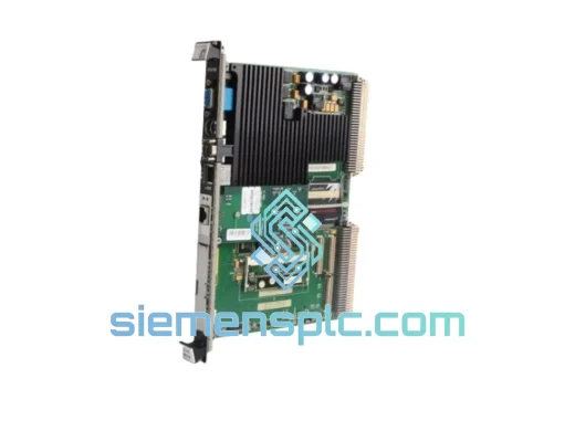
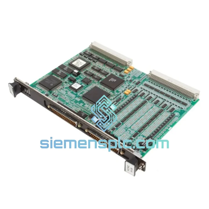
GE IS200VTURH1BAC Turbine Protection Card – Mark VI
Mark VI
Origin US
Turbine Protection Card
Request verified availability, condition, replacement risk review, packing options and courier lead time for IS210MVRAH1A.
Click Request Quote and the part number is inserted into the inquiry form automatically.
Core fields for model confirmation and RFQ routing. Detailed product narrative remains below.
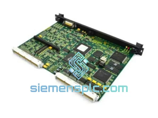
The IS210MVRAH1A is a Motor/Valve Relay Amplifier (MVRA) board engineered for GE’s Mark VIe turbine control platform. Within a Mark VIe I/O rack, this module occupies the relay-output tier of the distributed I/O hierarchy, translating low-level logic commands from the VCMI controller into galvanically isolated, relay-switched signals capable of driving motor starters, solenoid valves, and actuator coils in high-voltage field circuits. Its role is not peripheral — in a gas turbine startup sequence, the MVRA board governs the discrete switching events that sequence fuel valve opens, cooling fan motor energization, and lube oil pump starts. Timing errors at this layer propagate directly into turbine trip events or failed start sequences, making the electrical and firmware integrity of this module a first-order reliability concern.
Real-time Stock & RFQ: [email protected] | WhatsApp: +86 18359268345
| Parameter | Specification |
|---|---|
| Part Number | IS210MVRAH1A |
| Series | GE Mark VIe |
| Module Function | Motor/Valve Relay Amplifier (MVRA) |
| Manufacturer | General Electric — GE Vernova / GE Energy Controls |
| Form Factor | VME-style PCB, single-slot I/O rack module |
| System Supply Voltage | 24 VDC nominal (rack-supplied, ±10% tolerance) |
| Output Type | Relay-amplified discrete outputs — galvanically isolated |
| Output Contact Rating | Typically 2 A @ 120 VAC / 30 VDC resistive load per channel |
| Communication Interface | IONet — GE proprietary deterministic Ethernet backbone (100 Mbps) |
| Controller Compatibility | VCMI, VCRC, VTUR — Mark VIe controller family |
| Rack Mounting | Mark VIe VMIC I/O chassis — standard backplane connector |
| Operating Temperature | 0 °C to +60 °C (32 °F to 140 °F) |
| Storage Temperature | -40 °C to +85 °C |
| Relative Humidity | 5% to 95% non-condensing |
| EMC Compliance | IEC 61000-4-2 (ESD), IEC 61000-4-4 (EFT), IEC 61000-4-5 (Surge) |
| Functional Safety | IEC 61511 SIL-capable architecture; IEC 61508 alignment |
| Regulatory Marks | CE (EMC Directive 2014/30/EU, LVD 2014/35/EU), UL 508 |
| Weight | 1,540 g (approx.) |
| Warranty | 12 months against manufacturing defects from date of shipment |
The IS210MVRAH1A implements a two-stage signal path between the IONet-connected backplane and the field terminal block. In the first stage, the VCMI controller transmits a discrete output command over the IONet backbone at deterministic scan intervals — typically sub-5 ms cycle times in a standard Mark VIe rack configuration. The MVRA board’s onboard logic decodes this command and drives an intermediate solid-state switching element, which in turn energizes the relay coil in the second stage. This two-stage topology is deliberate: it prevents backplane logic voltages from ever appearing on field-side terminals, achieving galvanic isolation barriers rated to withstand transient voltages consistent with IEC 61000-4-5 Level 3 surge immunity (2 kV line-to-earth).
The relay output contacts themselves are arranged in a normally-open (NO) configuration for fail-safe de-energization behavior — a design choice aligned with IEC 61511 safety instrumented system principles, where loss of power or signal defaults the field device to a known safe state. Each relay channel incorporates arc suppression circuitry on the contact output, reducing contact erosion under inductive load switching — a critical consideration in motor starter and solenoid valve applications where inductive kickback voltages can reach 5–10× the supply voltage in unprotected circuits.
From an EMC standpoint, the PCB layout routes high-frequency IONet signals on inner copper layers with controlled impedance traces (typically 100 Ω differential), while relay coil drive lines are confined to outer layers with ground plane separation. This physical partitioning reduces capacitive coupling between the digital logic domain and the relay switching domain, maintaining signal integrity under the high-EMI conditions typical of turbine generator enclosures — where variable-frequency drives, high-current bus bars, and RF emissions from excitation systems coexist in close proximity.
The module also supports online diagnostics via the IONet interface. The VCMI controller can poll the MVRA board for relay contact feedback status, coil drive current confirmation, and board-level health registers. This diagnostic transparency allows the Mark VIe system to detect a welded relay contact or a failed coil drive circuit without requiring a physical inspection, enabling condition-based maintenance scheduling rather than time-based replacement cycles.
Every IS210MVRAH1A unit dispatched from our Xiamen, China facility undergoes a structured pre-shipment verification protocol. Visual inspection covers PCB surface condition, backplane connector pin integrity, relay body seating, and component-level anomaly screening against GE reference board photographs. Functional verification includes power-on continuity checks and, where test fixtures permit, IONet enumeration confirmation. Each unit is serialized and documented with its revision level, inspection date, and sourcing channel prior to packaging.
Units are sourced from decommissioned plant overhauls, authorized distributor surplus inventory, and OEM-certified refurbishment channels. No counterfeit or grey-market material is accepted into inventory. Original GE labeling, serial numbers, and revision markings are preserved intact on all units.
Packaging follows IEC 61340-5-1 ESD handling requirements: anti-static bag, foam-lined inner carton, and outer corrugated box with fragile and ESD-sensitive labeling. Export documentation — commercial invoice, packing list, and HS code 8537.10 classification — is prepared for all international shipments to facilitate customs clearance without delay. From Xiamen, air freight transit times to major industrial hubs are typically 3–7 business days to Europe, 5–10 days to the Americas, and 2–4 days to Southeast Asia. DHL, FedEx, and UPS express services are available. A 12-month warranty against manufacturing defects is provided from the date of shipment, with advance replacement available for qualified accounts on request.
Email: [email protected]
WhatsApp: +86 18359268345
Web: siemensplc.com
Location: Xiamen, China
© 2026 siemensplc.com. All rights reserved.
We check the full part number, brand, series and visible nameplate information before quotation.
Sales confirms stock path, condition option, quantity and realistic lead time for export dispatch.
DHL, FedEx, UPS or buyer courier arrangements can be reviewed with packing requirements.
Similar brand or category products for fast comparison and multi-item RFQ lists.