Mitsubishi Electric
RFQ Ready
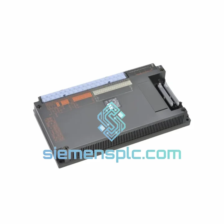
Mitsubishi RX312B BN634A589G53 I/O Module – MELSEC RX312
MELSEC
Origin JP
PLC I/O Module
Request verified availability, condition, replacement risk review, packing options and courier lead time for A0J2-E28AR.
Click Request Quote and the part number is inserted into the inquiry form automatically.
Core fields for model confirmation and RFQ routing. Detailed product narrative remains below.
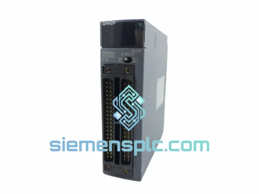
The Mitsubishi A0J2-E28AR is a 28-point relay output composite I/O unit engineered for the MELSEC A0J2 series programmable logic controller platform. Unlike discrete I/O modules that handle either inputs or outputs exclusively, the A0J2-E28AR consolidates both functions within a single housing, reducing backplane slot consumption and simplifying field wiring in compact control enclosures. Its relay output architecture makes it the preferred choice for applications requiring galvanic isolation between the controller logic domain and field-side loads operating at mixed AC/DC voltages.
Within the A0J2 control loop, this module occupies a critical position: it serves as the final actuator interface between the CPU’s scan-cycle decisions and the physical plant. The A0J2 CPU executes its ladder or instruction-list program, resolves output coil states, and writes the result to the output image register. The A0J2-E28AR reads that register via the proprietary A0J2 backplane bus and energizes or de-energizes the corresponding relay coil within one bus cycle. The mechanical relay contact then switches the field-side load — motor starter, solenoid valve, indicator lamp, or contactor coil — with full electrical isolation from the 5 VDC logic rail.
The composite architecture of the E28 designation means the 28 I/O points are distributed across both input and output channels within the same module body. This design is particularly valuable in retrofit and maintenance scenarios where panel real estate is fixed and adding separate input and output modules is not feasible. Engineers maintaining legacy A0J2 installations will find the A0J2-E28AR to be a direct, zero-modification replacement that preserves existing wiring, I/O addressing, and GX Developer program structures without any software migration overhead.
Real-time Stock & RFQ: [email protected] | WhatsApp: +86 18359268345
| Parameter | Specification |
|---|---|
| Model Number | A0J2-E28AR |
| Manufacturer | Mitsubishi Electric |
| Series | MELSEC A0J2 |
| Module Classification | Relay Output Composite I/O Unit |
| Total I/O Points | 28 points (composite input + output) |
| Output Type | Relay contact (Form A, SPST-NO) |
| Output Rated Current | 2 A per point (resistive load) |
| Max Switching Voltage | 250 V AC / 30 V DC |
| Min Switching Load | 10 mA at 5 V DC (reference value) |
| Relay Mechanical Life | ≥ 20,000,000 operations (no load) |
| Relay Electrical Life | ≥ 100,000 operations at rated load |
| Output Response Time (OFF→ON) | ≤ 10 ms (relay operate time) |
| Output Response Time (ON→OFF) | ≤ 12 ms (relay release time) |
| Input Rated Voltage | 24 V DC (input section) |
| Input ON Voltage | ≥ 19.2 V DC |
| Input OFF Voltage | ≤ 6 V DC |
| Input Impedance | Approx. 3.9 kΩ |
| Input Response Time | ≤ 10 ms (hardware filter) |
| Isolation Method | Photocoupler (input section); relay contact (output section) |
| Dielectric Withstand Voltage | 500 V AC for 1 minute (between I/O and internal logic) |
| Insulation Resistance | ≥ 10 MΩ at 500 V DC |
| Operating Temperature | 0°C to +55°C |
| Storage Temperature | -25°C to +75°C |
| Operating Humidity | 5% to 95% RH (non-condensing) |
| Vibration Resistance | 10–57 Hz: 0.075 mm amplitude; 57–150 Hz: 9.8 m/s² |
| Shock Resistance | 147 m/s², 3 times per axis |
| Compatible Base Units | A0J2-B5, A0J2-B8 |
| Compatible CPUs | A0J2CPU, A0J2HCPU |
| Bus Interface | A0J2 proprietary backplane bus |
| Module Weight | Approx. 740 g |
| Compliance | CE Marking, UL Listed (verify against current datasheet) |
| Warranty | 12 months from date of shipment |
Dual-domain isolation architecture. The A0J2-E28AR implements a strict two-stage isolation boundary. On the input side, each channel passes through a photocoupler with a forward current of approximately 5–10 mA, providing optical isolation between the 24 V DC field wiring and the 5 V DC logic bus. This photocoupler stage suppresses common-mode noise up to the dielectric withstand rating of 500 V AC, which is essential in environments where field cables run parallel to power conductors or variable-frequency drives generating high dV/dt transients. On the output side, the relay contact provides galvanic isolation between the logic domain and the switched load, eliminating any conductive path for ground loops or fault currents to propagate back into the CPU backplane.
Backplane bus arbitration and scan-cycle synchronization. The A0J2 backplane bus operates as a synchronous parallel bus. During each CPU scan cycle, the output image table is latched and transferred to the module’s output latch register via the bus. The A0J2-E28AR holds the relay states stable between bus refresh cycles, meaning field-side loads see a deterministic, glitch-free output state even during the CPU’s program execution phase. This latch-and-hold mechanism prevents spurious relay chatter that could otherwise occur if the relay driver were directly coupled to an asynchronous bus.
EMC design considerations. The relay coil driver circuit incorporates a flyback suppression diode across each coil to clamp the inductive kickback voltage generated when the relay de-energizes. Without this clamp, the collapsing magnetic field would produce voltage spikes of several hundred volts on the 5 V logic rail, potentially corrupting adjacent module logic or triggering false interrupts in the CPU. The module’s PCB layout routes high-current relay drive traces away from the low-level signal traces of the input photocoupler section, reducing capacitive coupling between the two domains. The metal housing provides an additional Faraday shield against radiated EMI from external sources.
Composite I/O addressing on the A0J2 bus. The A0J2-E28AR occupies a defined slot address on the base unit. The CPU’s I/O assignment table maps the 28 points to consecutive Y (output) and X (input) device addresses based on slot position. This addressing is fixed in hardware and requires no software configuration beyond the initial I/O assignment in GX Developer. The deterministic address mapping simplifies program maintenance and reduces the risk of addressing errors during module replacement.
Every A0J2-E28AR unit supplied through siemensplc.com is sourced as genuine Mitsubishi Electric original hardware. Units are procured through verified supply channels with full OEM traceability documentation available upon request. Prior to dispatch, each module undergoes a structured inspection protocol: visual examination of the housing, connector pins, and label integrity; functional verification of relay operation on all output channels; and photocoupler continuity check on all input channels. Units that do not pass inspection are quarantined and not shipped.
Packaging uses anti-static foam inserts and moisture-barrier bags to protect the module’s PCB and relay contacts during transit. Outer cartons are rated for international air and sea freight handling. All shipments originate from our warehouse in Xiamen, China, a major logistics hub with direct access to international express carriers including DHL, FedEx, and UPS, as well as sea freight consolidation services for bulk orders. Standard international express delivery to most destinations in Europe, North America, Southeast Asia, and the Middle East is achieved within 3–7 business days. Expedited next-flight-out options are available for critical production downtime situations.
A 12-month warranty from the date of shipment covers manufacturing defects and functional failures under normal operating conditions. Warranty claims are processed with a target response time of 48 hours. Replacement units are dispatched upon confirmation of the defect, minimizing production impact. Customs documentation, including commercial invoices, packing lists, and certificates of origin, is prepared in compliance with destination country import requirements to prevent clearance delays.
Email: [email protected]
WhatsApp: +86 18359268345
Web: siemensplc.com
Location: Xiamen, China
© 2026 siemensplc.com. All rights reserved.
We check the full part number, brand, series and visible nameplate information before quotation.
Sales confirms stock path, condition option, quantity and realistic lead time for export dispatch.
DHL, FedEx, UPS or buyer courier arrangements can be reviewed with packing requirements.
Similar brand or category products for fast comparison and multi-item RFQ lists.