Mitsubishi Electric
RFQ Ready
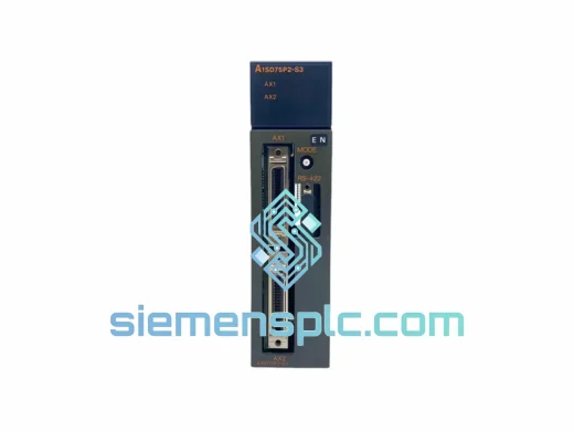
Mitsubishi A1SD75P2-S3 PLC Positioning Module
MELSEC-A
Origin JP
PLC Positioning Module
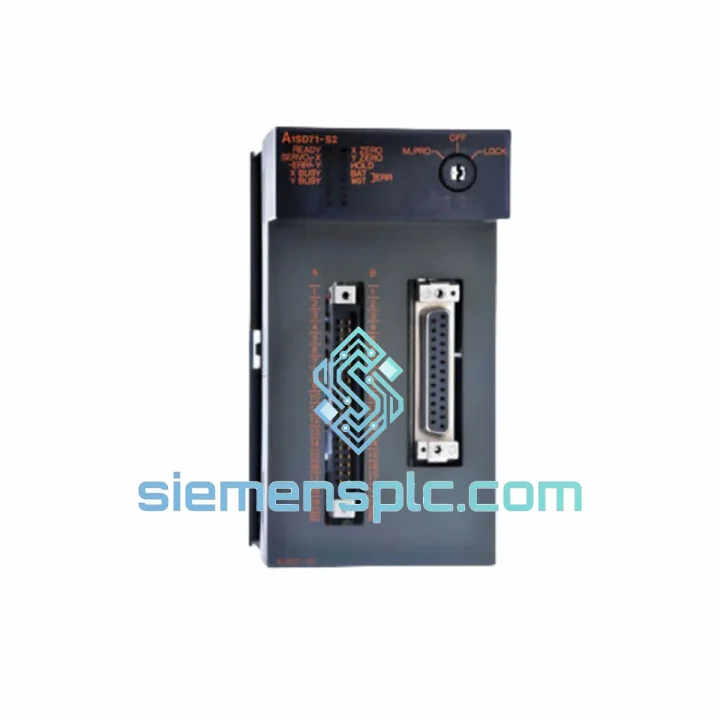
Request verified availability, condition, replacement risk review, packing options and courier lead time for A1SD71-S2.
Click Request Quote and the part number is inserted into the inquiry form automatically.
Core fields for model confirmation and RFQ routing. Detailed product narrative remains below.
Your MELSEC-A line is stopped. The A1SD71-S2 positioning module has failed, and your production scheduler is already calling. You don’t need a sales pitch — you need the part, verified, boxed, and moving toward your dock today. That’s exactly what we do.
We stock the Mitsubishi A1SD71-S2 in Xiamen, China. Every unit on our shelf has been power-on tested in a live MELSEC-A rack before it earns a place in our inventory. When you place an order before 15:00 CST, it leaves our warehouse the same day via DHL Express or FedEx International Priority. Most destinations in Southeast Asia receive within 48 hours. Europe and North America: 72–96 hours door to door.
One failed positioning module should not cost you a full production shift. It won’t — not if you call us first.
URGENT REQUIREMENT? Contact: [email protected] | WhatsApp: +86 18359268345
| Parameter | Specification | Status |
|---|---|---|
| Model Number | A1SD71-S2 | ✔ Ready to Ship |
| Manufacturer | Mitsubishi Electric Corporation | 100% Original OEM |
| Platform | MELSEC-A Series (A1S / A2 / A3 base units) | |
| Module Function | Single-Axis Positioning Control | |
| Output Method | Pulse train — CW/CCW or PULSE/SIGN selectable | |
| Max. Pulse Output Frequency | 200 kpps | |
| Positioning Data Points | 600 points (-S2 enhanced variant) | |
| Control Modes | Position, Speed, Speed-to-Position switching | |
| Manual Operation | JOG + MPG (manual pulse generator) input | |
| Homing Methods | DOG-type, Data-set type, Stopper-type | |
| External I/O | DOG, STOP, FLS/RLS limit switches, CLEAR | |
| CPU Interface | A-bus backplane via FROM/TO buffer memory | |
| Power Supply | DC 5 V from base unit backplane | |
| Current Draw | 0.55 A @ 5 VDC | |
| Operating Temperature | 0 °C to 55 °C | |
| Storage Temperature | −20 °C to 75 °C | |
| Humidity | 10–90 % RH, non-condensing | |
| Vibration Resistance | 10–57 Hz: 0.075 mm / 57–150 Hz: 9.8 m/s² | |
| Shock Resistance | 147 m/s², 3× per axis | |
| Compatible Servo Amplifiers | MR-J2S, MR-J3, MR-E; 3rd-party pulse-input drives | |
| Programming Tool | GX Developer / GPP-W | |
| Country of Origin | Japan | |
| Weight | Approx. 0.4 kg |
Ten years of field calls on MELSEC-A positioning modules teach you the same lessons repeatedly. Here’s what actually matters when you’re swapping an A1SD71-S2 under pressure:
1. Confirm the fault is the module, not the servo amplifier or wiring.
Before pulling the A1SD71-S2, check the servo amplifier alarm code first. A pulse-loss alarm (e.g., MR-J2S AL.52) with no mechanical obstruction often points to a degraded pulse output driver on the positioning module — but verify by temporarily connecting a frequency counter or oscilloscope to the PULSE+ / SIGN+ terminals. If you see no output at all during a JOG command, the module’s output stage has failed. If output is present but erratic, check the cable shield grounding at the CN1 connector before condemning the module.
2. Buffer memory address mapping — don’t skip this step.
The A1SD71-S2 uses a dedicated buffer memory map accessed via FROM/TO instructions. When installing a replacement, the CPU program references the module’s slot number (X/Y device assignment). If the replacement is seated in a different slot than the failed unit, every FROM/TO address offset in your ladder program must be recalculated. Seat the new module in the identical slot position as the original to avoid a full program audit.
3. Output mode switch — CW/CCW vs. PULSE/SIGN.
Buffer memory address UnG0 (Pr.1) defines the pulse output mode. The factory default is CW/CCW. If your servo amplifier expects PULSE/SIGN (common on Yaskawa and Panasonic drives used in mixed-brand retrofits), you must write the correct value to Pr.1 before issuing a start command. A mode mismatch causes the axis to run away at full speed in one direction — a dangerous condition on any machine with hard travel limits.
4. Home position return after replacement.
The A1SD71-S2 does not retain current position data through a power cycle or module swap. After installing the replacement, a full home position return (OPR) is mandatory before any automatic operation. Skipping this step and issuing an absolute position command will drive the axis to a mechanically incorrect position. Use DOG-type OPR if a proximity switch is installed; use data-set type OPR if the machine uses a direct-drive encoder with a known reference mark.
5. Common error codes and their field meaning:
6. Firmware and hardware revision matching.
The A1SD71-S2 has gone through multiple PCB revisions over its production life. In most cases, revisions are backward-compatible. However, if your application uses undocumented buffer memory addresses or relies on specific timing behavior documented in a particular version of IB-66544, confirm the PCB revision marking on the module’s label before installation. Contact us and we’ll match the revision if you specify it in your order.
The A1SD71-S2 was engineered for the factory floor, not a server room. Mitsubishi Electric designed the MELSEC-A series to operate continuously in environments that would kill consumer-grade electronics within weeks.
Vibration: The module’s PCB uses conformal coating and through-hole component construction in critical signal paths. It meets IEC 61131-2 vibration requirements: 10–57 Hz at 0.075 mm displacement, 57–150 Hz at 9.8 m/s² acceleration. In practice, this means it survives installation on press frames, compressor skids, and conveyor drive panels without connector fatigue or solder joint cracking — failure modes that plague cheaper alternatives.
Thermal cycling: Rated for 0–55 °C continuous operation with storage down to −20 °C. The solid-state pulse output driver has no electromechanical components subject to thermal wear. Units that have been in service for 15+ years in foundry environments routinely pass our power-on test without any remediation — a testament to the original design margin.
Humidity and contamination: The 10–90 % RH non-condensing rating covers most tropical and coastal industrial environments. The module’s gold-plated backplane connector maintains contact resistance below 30 mΩ even after years of thermal cycling in humid conditions. If your installation environment involves condensation risk, we recommend a panel heater to keep the enclosure above the dew point — the module itself will handle the rest.
EMI immunity: The A-bus backplane provides inherent shielding for the module’s internal logic. The pulse output lines should be routed in shielded cable with the shield grounded at the servo amplifier end only (single-point grounding). Improper shield grounding is the single most common cause of intermittent positioning errors in otherwise healthy systems — not module failure.
Our warehouse is located in Xiamen, Fujian Province — one of China’s primary export hubs with direct access to Xiamen Gaoqi International Airport and Xiamen Port. This geography is not accidental. It gives us same-day handoff to DHL Express, FedEx International Priority, and UPS Worldwide Express cut-off times that most inland Chinese suppliers cannot match.
Standard dispatch process:
Typical transit times from Xiamen:
Every shipment includes full insurance coverage at declared value. For orders above USD 2,000, we provide a dedicated shipment coordinator who monitors the consignment through customs clearance and contacts you proactively if any documentation issue arises at the destination port. We have handled emergency shipments to active production shutdowns in 23 countries — we know what it takes to get a part through customs fast.
Sea freight consolidation (LCL/FCL) is available for bulk orders of 10+ units or mixed-SKU orders where air freight cost is prohibitive. Lead time for sea freight: 12–18 days port to port, Xiamen to major global ports.
Email: [email protected]
WhatsApp: +86 18359268345
Web: siemensplc.com
© 2026 siemensplc.com. All rights reserved.
We check the full part number, brand, series and visible nameplate information before quotation.
Sales confirms stock path, condition option, quantity and realistic lead time for export dispatch.
DHL, FedEx, UPS or buyer courier arrangements can be reviewed with packing requirements.
Similar brand or category products for fast comparison and multi-item RFQ lists.