Mitsubishi Electric
RFQ Ready
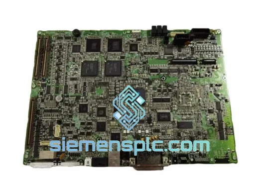
Mitsubishi YZ311B BU778A011G53A DCS Motherboard
MELSEC
Origin JP
DCS Motherboard
Request verified availability, condition, replacement risk review, packing options and courier lead time for MELSEC-A.
Click Request Quote and the part number is inserted into the inquiry form automatically.
Core fields for model confirmation and RFQ routing. Detailed product narrative remains below.
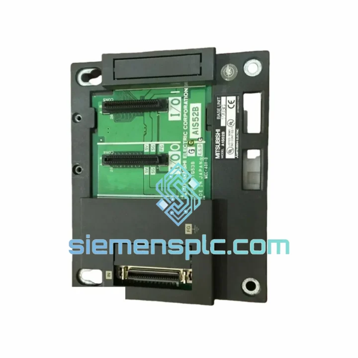
The Mitsubishi Electric A1S52B is a 5-slot extension base unit engineered for the MELSEC-A Series programmable controller platform. Within a distributed I/O architecture, the A1S52B functions as a passive backplane segment that extends the module-mounting capacity of the main base unit (e.g., A1S-55B or A1S-65B) via a dedicated extension cable interface. Each slot on the A1S52B provides a standardized 64-pin connector bus that carries both the internal data bus and the 5 VDC/24 VDC power rails sourced from the rack-mounted power supply module. The unit does not contain active logic; its role is to provide a mechanically rigid, electrically stable mounting platform that preserves bus signal integrity across the extension chain.
In multi-rack MELSEC-A configurations, the CPU module on the main base arbitrates all I/O refresh cycles across every connected extension base. The A1S52B participates in this scan cycle passively — modules seated in its slots are addressed by the CPU through the extension cable as if they were local to the main rack. This transparent addressing model means that I/O module configuration, parameter assignment, and diagnostic polling require no additional programming overhead beyond what is already defined in the CPU’s I/O assignment table. Engineers working on legacy MELSEC-A installations can therefore add an A1S52B to an existing system without modifying the ladder logic structure, provided the total I/O point count remains within the CPU’s addressable range.
The physical construction of the A1S52B uses a die-cast aluminum chassis with integrated DIN rail mounting brackets and panel-mount screw holes. The slot rail guides are machined to tight tolerances to ensure positive module seating and reliable backplane connector engagement. The extension connector, located on the right-hand face of the unit, accepts the AC10B (1 m) or AC30B (3 m) extension cable, which carries the parallel bus signals between racks. Signal integrity on this cable is maintained through differential line driving on the data bus lines, which provides common-mode noise rejection in environments with high electromagnetic interference from variable-frequency drives, servo amplifiers, and high-current switching equipment.
The A1S52B requires a dedicated MELSEC-A Series power supply module — either the A1S61PN (100–240 VAC input, 5 VDC/6 A output) or the A1S62PN (24 VDC input) — installed in the leftmost slot of the rack. This power supply module is not shared with the main base; each extension rack operates with its own independent power budget. The 5 VDC bus current capacity of the installed power supply module defines the maximum number and type of I/O modules that can be populated in the remaining four slots. Engineers must calculate the aggregate 5 VDC consumption of all installed modules against the power supply’s rated output current before finalizing the rack configuration.
Up to seven A1S52B extension base units can be cascaded from a single MELSEC-A CPU, depending on the specific CPU model and its maximum I/O point specification. The extension cable length between consecutive racks must not exceed the rated maximum (3 m per segment for the AC30B), and the total cumulative cable length across all extension stages is subject to the bus propagation delay budget defined in the MELSEC-A hardware manual. Exceeding these limits results in bus timing violations that manifest as intermittent I/O read errors or CPU hardware error codes — faults that are difficult to diagnose without oscilloscope-level bus analysis.
Real-time Stock & RFQ: [email protected] | WhatsApp: +86 18359268345
| Part Number / SKU | A1S52B |
| Manufacturer | Mitsubishi Electric |
| Series | MELSEC-A (AnS Sub-Series) |
| Product Type | Extension Base Unit (Passive Expansion Rack) |
| Number of Module Slots | 5 slots (including 1 dedicated power supply slot) |
| Available I/O Module Slots | 4 slots (after power supply installation) |
| Backplane Bus Width | 8-bit parallel data bus, MELSEC-A proprietary protocol |
| Extension Connector Type | Proprietary 64-pin edge connector (right-side output) |
| Compatible Extension Cables | AC10B (1 m), AC30B (3 m) |
| Compatible CPU Series | A1SCPU, A2SCPU, A3SCPU, A0J2HCPU (MELSEC-A/AnS) |
| Power Supply Slot | Slot 0 (leftmost) — dedicated, not shareable |
| Power Supply Compatibility | A1S61PN (AC input), A1S62PN (DC input) |
| 5 VDC Bus Current (max) | Determined by installed power supply module rating |
| Mounting Method | 35 mm DIN rail or M4 panel-mount screws |
| Operating Temperature | 0 °C to +55 °C |
| Storage Temperature | –20 °C to +75 °C |
| Relative Humidity | 5% to 95% RH, non-condensing |
| Vibration Resistance | IEC 61131-2 / JIS B 3502 compliant |
| Shock Resistance | 147 m/s² (15 G), 11 ms half-sine pulse |
| Enclosure Rating | IP20 (open-frame, panel-mount installation required) |
| Unit Weight | 1,380 g (without modules) |
| Certifications | CE (EMC Directive), UL 508, cUL, RoHS |
| Country of Origin | Japan |
| Warranty | 12 months against manufacturing defects |
The A1S52B’s backplane is a passive PCB assembly with no active logic ICs. The 64-pin edge connectors at each slot position are wired in parallel to the extension bus, meaning all modules share the same address/data lines. Module selection is achieved through slot-position-encoded chip-select signals generated by the CPU during each I/O refresh scan. This architecture imposes a deterministic scan time contribution per extension rack — typically 0.1 ms to 0.3 ms per rack depending on the number of populated slots and the I/O module types installed.
EMC performance of the A1S52B is governed by the chassis ground plane, which is a continuous copper pour on the backplane PCB connected to the DIN rail mounting bracket and the chassis earth terminal. This ground plane provides a low-impedance return path for high-frequency noise currents induced by adjacent switching equipment. The extension cable shield is terminated at both ends to this chassis ground, forming a Faraday shield around the bus signals during inter-rack transmission. In installations where the A1S52B is mounted in a panel with high-power servo drives, the chassis earth bonding impedance should be verified to be below 0.1 Ω at DC to ensure the EMC ground plane functions as designed.
The slot rail guides incorporate a keying mechanism that prevents incorrect module insertion orientation. The backplane connector uses gold-plated contacts rated for a minimum of 100 insertion/removal cycles, which is relevant for MRO operations where modules are frequently swapped during troubleshooting. The power supply slot (Slot 0) has a dedicated connector with higher current-rated contacts to handle the 5 VDC/6 A bus supply current without contact resistance-induced voltage drop.
Every Mitsubishi Electric A1S52B unit supplied by siemensplc.com is sourced as genuine OEM hardware through verified industrial distribution channels. Each unit undergoes a structured pre-dispatch inspection protocol:
Logistics operations are based in Xiamen, China, with access to international express freight services (DHL, FedEx, UPS) and sea freight consolidation for bulk orders. Standard express delivery to major industrial hubs in Southeast Asia, the Middle East, Europe, and North America is typically achieved within 3–7 business days. Export documentation including commercial invoice, packing list, and certificate of origin is prepared for all international shipments.
Email: [email protected]
WhatsApp: +86 18359268345
Web: siemensplc.com
Location: Xiamen, China
© 2026 siemensplc.com. All rights reserved.
We check the full part number, brand, series and visible nameplate information before quotation.
Sales confirms stock path, condition option, quantity and realistic lead time for export dispatch.
DHL, FedEx, UPS or buyer courier arrangements can be reviewed with packing requirements.
Similar brand or category products for fast comparison and multi-item RFQ lists.