Mitsubishi Electric
RFQ Ready
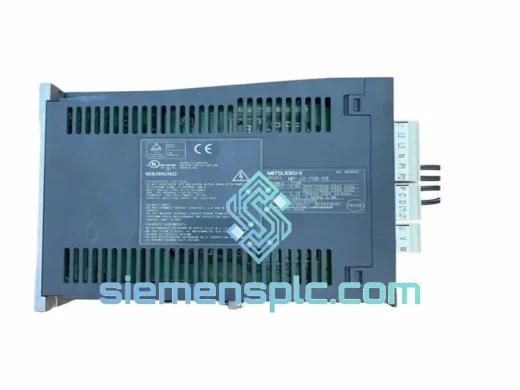
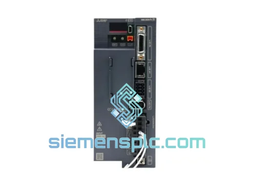
Mitsubishi MR-JE-70C AC Servo Amplifier
MELSERVO-JE CC-Link IE
Origin JP
AC Servo Amplifier
Request verified availability, condition, replacement risk review, packing options and courier lead time for MR-J3CN1.
Click Request Quote and the part number is inserted into the inquiry form automatically.
Core fields for model confirmation and RFQ routing. Detailed product narrative remains below.
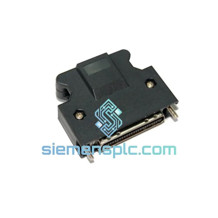
The Mitsubishi MR-J3CN1 is the OEM-designated 50-pin CN1 signal connector engineered specifically for the MR-J3 series servo amplifier platform. Within a closed-loop servo control architecture, the CN1 port is the primary signal gateway between the motion controller (or host PLC) and the servo amplifier’s command processing stage. Every pulse train command, analog speed/torque reference, digital I/O handshake, and encoder feedback signal passes through this interface. Connector integrity at this node is not a peripheral concern — it is a deterministic factor in servo system accuracy and uptime.
The MR-J3CN1 is not a generic 50-pin D-sub assembly. It is manufactured to Mitsubishi Electric’s internal mechanical and electrical tolerances, ensuring that contact resistance, shielding continuity, and mating force specifications align precisely with the CN1 receptacle on MR-J3-□A (pulse/analog) and MR-J3-□B (SSCNET III) amplifier variants. Substituting with non-OEM connectors introduces measurable risk: elevated contact resistance degrades analog command fidelity, incomplete shield termination increases susceptibility to common-mode noise on high-speed pulse inputs, and dimensional non-conformance can cause intermittent contact under vibration — all failure modes that manifest as position error, servo alarm, or unexplained axis deviation during production.
This connector is stocked at our Xiamen, China facility and ships globally. For real-time availability and volume pricing, contact [email protected] or WhatsApp +86 18359268345.
Real-time Stock & RFQ: [email protected] | WhatsApp: +86 18359268345
| Parameter | Specification |
|---|---|
| Part Number | MR-J3CN1 |
| Manufacturer | Mitsubishi Electric Corporation |
| Compatible Series | MR-J3-□A, MR-J3-□B Servo Amplifiers |
| Connector Port | CN1 (Command / I/O Signal Interface) |
| Pin Count | 50-pin |
| Signal Types Supported | Pulse train (open collector / differential), Analog ±10 V, Digital I/O (24 VDC) |
| Shield Termination | Integrated shell with 360° cable shield clamp |
| Mating Cycles (rated) | ≥ 500 insertions per IEC 60603-9 class |
| Contact Material | Gold-plated over phosphor bronze |
| Operating Temperature | -20 °C to +70 °C |
| Vibration Resistance | Compliant with JIS B 3502 / IEC 61131-2 vibration class |
| Applicable Wire Gauge | AWG 24–28 shielded twisted-pair (per MR-J3 wiring manual) |
| Weight (connector only) | Approx. 85 g |
| Country of Origin | Japan |
| Quality Warranty | 12 months from date of shipment |
The CN1 interface on the MR-J3 amplifier handles three electrically distinct signal classes simultaneously: high-frequency differential pulse inputs (up to 4 Mpps for position command), low-level analog references (±10 V at source impedances of 10–50 kΩ), and 24 VDC digital I/O for servo-on, alarm-reset, and limit switch logic. Managing these three classes within a single 50-pin connector body without cross-coupling requires deliberate physical partitioning of the pin field and robust common-mode rejection at the shell level.
The MR-J3CN1 shell is a die-cast zinc alloy body with a conductive chromate finish, providing a low-impedance ground path from the cable shield braid to the amplifier chassis ground via the mating receptacle’s shell contacts. This 360° shield termination suppresses common-mode noise ingress on differential pulse lines — a critical design requirement when the servo drive cabinet shares a panel with variable-frequency drives or switching power supplies that generate conducted EMI in the 150 kHz–30 MHz band. Without continuous shield termination at the connector body, differential-mode noise rejection on the pulse input stage degrades, and the amplifier’s position deviation counter can accumulate spurious counts, producing axis drift that is difficult to distinguish from mechanical backlash.
The gold-plated contacts maintain stable contact resistance below 10 mΩ across the rated mating cycle life. For analog command signals, a 1 mΩ variation in contact resistance at a 10 kΩ source impedance produces a speed reference error of 0.01% — negligible in most applications, but relevant in tension-control and winding applications where speed regulation tighter than 0.1% is specified. The OEM contact geometry ensures the normal force and wipe distance remain within the design envelope, which is not guaranteed with aftermarket connector bodies manufactured to looser dimensional tolerances.
The strain relief clamp integrated into the MR-J3CN1 body constrains cable movement at the point of entry, preventing cyclic flexing of the conductor terminations during machine vibration. In high-cycle applications — packaging lines running 200+ cycles per minute, for example — unsupported cable movement at the connector entry is a documented failure mode that causes intermittent open circuits on I/O lines, triggering nuisance servo alarms and unplanned downtime.
Every MR-J3CN1 unit supplied by siemensplc.com is sourced through verified industrial distribution channels and carries Mitsubishi Electric’s original part marking and packaging. Mitsubishi Electric’s manufacturing operations for servo accessories are conducted under ISO 9001-certified quality management systems, with outgoing inspection covering dimensional conformance, contact resistance, and mating force verification.
Upon receipt at our Xiamen, China warehouse, each batch undergoes incoming inspection: physical integrity check, part number label verification, and ESD-safe storage assignment. Units are held in climate-controlled conditions (temperature 15–30 °C, relative humidity <70% non-condensing) to prevent contact oxidation during storage. Shipment documentation — including packing list, commercial invoice, and certificate of origin — is prepared to support customs clearance in major import markets including the EU, USA, Southeast Asia, and the Middle East.
Standard international dispatch from Xiamen is via DHL Express, FedEx International Priority, or UPS Worldwide Expedited, with typical transit times of 3–7 business days to most destinations. For urgent MRO requirements, same-day dispatch is available for orders confirmed before 14:00 CST. Air freight consolidation and sea freight options are available for volume orders. All shipments are fully insured and tracked from dispatch to delivery confirmation.
A 12-month warranty from the date of shipment covers manufacturing defects. Warranty claims are processed with replacement dispatch within 5 business days of defect confirmation. Batch traceability documentation is available upon request for OEM and system integrator customers requiring incoming inspection records.
📧 Email: [email protected]
📱 WhatsApp: +86 18359268345
🌐 Web: siemensplc.com
📍 Location: Xiamen, China
© 2026 siemensplc.com. All rights reserved.
We check the full part number, brand, series and visible nameplate information before quotation.
Sales confirms stock path, condition option, quantity and realistic lead time for export dispatch.
DHL, FedEx, UPS or buyer courier arrangements can be reviewed with packing requirements.
Similar brand or category products for fast comparison and multi-item RFQ lists.