Mitsubishi Electric
RFQ Ready
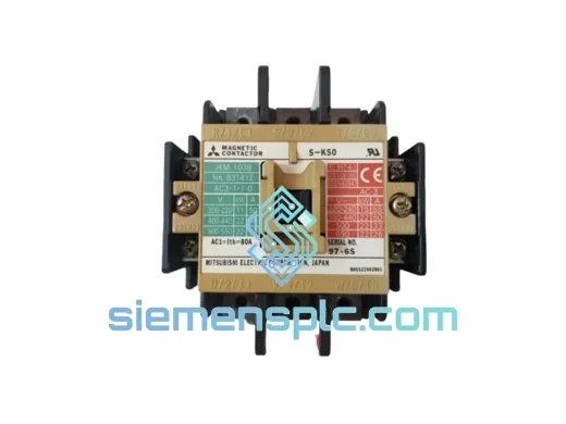
Mitsubishi S-K50/S-K65 Magnetic Contactor
Origin JP
Magnetic Contactor
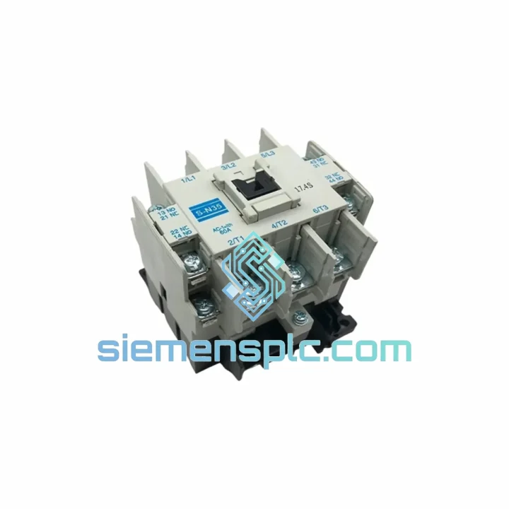
Request verified availability, condition, replacement risk review, packing options and courier lead time for S-N35.
Click Request Quote and the part number is inserted into the inquiry form automatically.
Core fields for model confirmation and RFQ routing. Detailed product narrative remains below.
The Mitsubishi Electric S-N35 is a 35 A rated IEC magnetic contactor designed for three-phase AC motor switching in utilization category AC-3 (squirrel-cage motor starting and switching during running). Operating within the S-N series platform, this device integrates a laminated silicon-steel electromagnet core, silver-cadmium oxide (AgCdO) or silver-tin oxide (AgSnO₂) main contacts, and a double-break contact geometry that collectively deliver consistent arc extinction across the rated voltage range of up to 690 V AC. The S-N35 is deployed in motor control centers (MCC), standalone starter panels, and distributed control cabinets where deterministic switching behavior and long contact service life are non-negotiable engineering requirements.
At 35 A AC-3 continuous current, the S-N35 handles motor loads up to 18.5 kW at 400 V or 22 kW at 415 V without derating under standard ambient conditions (up to 40 °C). The coil circuit accepts multiple control voltages — 24 V AC/DC, 110 V AC, 220 V AC, and 380 V AC — allowing a single hardware SKU to serve diverse panel designs without stocking multiple coil variants. An integrated economizer circuit reduces the holding coil current after pull-in, lowering steady-state power dissipation and reducing thermal load inside sealed enclosures.
The modular architecture of the S-N series is a key differentiator in panel engineering. Snap-on auxiliary contact blocks (e.g., S-N11 add-on blocks providing up to 4 auxiliary poles), surge suppressors (RC type or varistor type), and mechanical interlock kits attach directly to the contactor body without rewiring or additional mounting hardware. This field-expandability reduces panel modification time during commissioning and simplifies future upgrades when control logic requirements change.
Terminal connectivity supports both screw-clamp and spring-clamp wiring options. Spring-clamp terminals maintain consistent contact force independent of conductor relaxation or vibration, a critical factor in mobile equipment, compressor skids, and offshore installations where mechanical shock is a routine operating condition. Wire acceptance ranges from 1.5 mm² to 16 mm² (AWG 14–6) on main terminals, accommodating standard industrial cable cross-sections without the need for ferrule adapters on smaller conductors.
Mounting is compatible with 35 mm DIN rail (EN 60715) or direct screw mounting on a back plate, giving panel builders flexibility in cabinet layout. The compact footprint — approximately 55 mm wide — allows high-density installation in standard 400 mm wide enclosures. The S-N35 is certified to IEC 60947-4-1 and JIS C 8201-4-1, carries CE marking for EEA installations, and is RoHS compliant. UL/CSA listed variants are available for North American projects upon specification.
Real-time Stock & RFQ: [email protected] | WhatsApp: +86 18359268345
| Model / SKU | S-N35 |
| Brand | Mitsubishi Electric |
| Series | S-N Series (IEC Magnetic Contactors) |
| Utilization Category | AC-3 (IEC 60947-4-1) |
| Rated Operational Current (AC-3) | 35 A |
| Motor Rating at 400 V AC | 18.5 kW / 25 HP |
| Motor Rating at 415 V AC | 22 kW |
| Rated Insulation Voltage (Ui) | 690 V AC |
| Rated Impulse Withstand Voltage (Uimp) | 6 kV |
| Coil Control Voltage Options | 24 V AC/DC, 110 V AC, 220 V AC, 380 V AC |
| Coil Frequency | 50/60 Hz |
| Main Poles | 3 |
| Standard Auxiliary Contacts | 1NO + 1NC |
| Max. Auxiliary Contacts (with add-on blocks) | Up to 4 poles |
| Mechanical Endurance | 10,000,000 operations |
| Electrical Endurance (AC-3) | 1,500,000 operations |
| Operating Frequency | Up to 1,200 operations/hour |
| Ambient Temperature (Operation) | -5 °C to +60 °C (derated above 40 °C) |
| Storage Temperature | -40 °C to +70 °C |
| Enclosure Protection | IP20 (open type) |
| Mounting | 35 mm DIN rail (EN 60715) or screw mounting |
| Main Terminal Wire Range | 1.5–16 mm² (AWG 14–6) |
| Weight | 1,210 g |
| Standards | IEC 60947-4-1, JIS C 8201-4-1, CE, RoHS |
| Country of Origin | Japan |
| Warranty | 12 months from date of shipment |
The S-N35 electromagnet assembly uses a laminated silicon-steel E-I core with a shading ring on the stationary pole face. The shading ring — a short-circuited copper band — generates a phase-shifted flux component that prevents the 100/120 Hz mechanical vibration (chatter) inherent in single-phase AC coil excitation. This is not a software-controlled feature; it is a passive electromagnetic design that operates without any control electronics, making it immune to firmware faults or communication failures.
The main contact material is silver-tin oxide (AgSnO₂), selected over traditional silver-cadmium oxide (AgCdO) for its superior arc erosion resistance and compliance with RoHS restrictions on cadmium. AgSnO₂ contacts exhibit a harder surface oxide layer that resists contact welding under high inrush current conditions — a critical property when switching motors with high locked-rotor current (LRC) multiples of 6–8× FLA. The double-break contact geometry divides the arc voltage across two contact gaps in series, reducing the energy per gap and extending contact service life toward the rated 1,500,000 AC-3 operations.
EMC performance is addressed at the coil circuit level. The optional RC surge suppressor (connected across the coil terminals) clamps the inductive kick voltage generated at coil de-energization to below 1,000 V peak, protecting adjacent PLC digital output modules from transient overvoltage. For DC coil variants (24 V DC), a freewheeling diode suppressor is the preferred solution, reducing the release time compared to RC suppression and allowing faster contactor dropout in safety-critical applications. The coil economizer circuit — where fitted — switches from a high pull-in current to a reduced holding current within approximately 50 ms of pull-in, reducing coil temperature rise by 15–25 °C under continuous duty, which directly extends coil insulation life per the Arrhenius thermal aging model.
The mechanical interlock kit (sold separately) uses a rigid plastic lever that physically prevents both contactors in a reversing starter from closing simultaneously, independent of the electrical interlock implemented in the PLC or relay logic. This hardware-level interlock provides a fail-safe against phase-to-phase short circuits that could result from simultaneous main contact closure in forward/reverse configurations.
Every Mitsubishi Electric S-N35 unit supplied by siemensplc.com is sourced through verified industrial distribution channels and undergoes a structured incoming inspection protocol at our Xiamen, China facility. Physical inspection covers label authenticity, housing integrity, contact gap verification, and coil resistance measurement against factory specification tolerances. Units are stored in climate-controlled, ESD-safe warehousing to prevent humidity-induced contact oxidation and coil insulation degradation during storage.
Shipment from Xiamen is executed via DHL Express, FedEx International Priority, or UCP air freight depending on order volume and destination. In-stock orders are processed and dispatched within 1–3 business days of payment confirmation. Export documentation — including commercial invoice, packing list, and certificate of origin — is prepared in compliance with destination country import requirements. HS Code 8536.49 applies to magnetic contactors for voltage not exceeding 1,000 V. For orders requiring expedited customs clearance, pre-shipment documentation can be provided electronically within 24 hours of order confirmation.
All units carry a 12-month warranty from the date of shipment, covering manufacturing defects in materials and workmanship. Warranty claims are processed with photographic evidence of the defect and the original shipment documentation. Replacement units are dispatched from Xiamen stock within 3 business days of claim approval. siemensplc.com does not supply refurbished, remanufactured, or grey-market components; all products are new, original-manufacture units with intact factory seals and documentation.
Email: [email protected]
WhatsApp: +86 18359268345
Web: siemensplc.com
Location: Xiamen, China
© 2026 siemensplc.com. All rights reserved.
We check the full part number, brand, series and visible nameplate information before quotation.
Sales confirms stock path, condition option, quantity and realistic lead time for export dispatch.
DHL, FedEx, UPS or buyer courier arrangements can be reviewed with packing requirements.
Similar brand or category products for fast comparison and multi-item RFQ lists.