Siemens
RFQ Ready
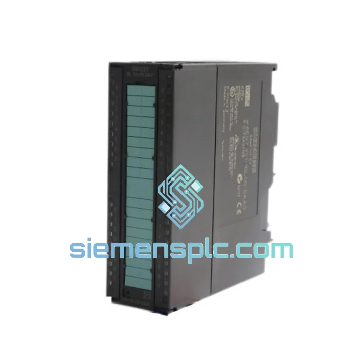
Siemens 6ES7321-1BL00-0AA0 Digital Input Module
SIMATIC
Origin DE
PLC Digital Input Module
Request verified availability, condition, replacement risk review, packing options and courier lead time for 6ES7321-1FH00-0AA0.
Click Request Quote and the part number is inserted into the inquiry form automatically.
Core fields for model confirmation and RFQ routing. Detailed product narrative remains below.
The 6ES7321-1FH00-0AA0 is a 16-channel digital input module belonging to the SM321 signal module family within the Siemens SIMATIC S7-300 programmable logic controller platform. It serves as the primary field-signal acquisition interface between 24 VDC two-wire and three-wire sensors, mechanical contacts, and proximity switches, and the S7-300 CPU’s process image input (PII) table. The module occupies a single 40 mm slot on the DIN-rail-mounted S7-300 rack and communicates with the CPU exclusively via the K-bus backplane, drawing a maximum of 50 mA at 5 VDC from the bus — a load profile that allows dense rack configurations without exceeding power supply budgets on standard PS307 units.
In a control loop context, this module sits at the data-acquisition boundary. Every scan cycle, the CPU reads the 16-bit input image from the module’s K-bus interface register and maps it to the configured %I address range in the process image. The configurable input delay — selectable at 0.1, 0.5, 3, or 15 ms via STEP 7 or TIA Portal hardware configuration — determines the minimum pulse width that the module will register as a valid logic-1 transition. This parameter is critical: setting 0.1 ms enables capture of high-frequency proximity switch outputs, while 15 ms suppresses contact bounce from mechanical limit switches without requiring external RC debounce circuits.
Real-time Stock & RFQ: [email protected] | WhatsApp: +86 18359268345
| Parameter | Specification |
|---|---|
| Order Number (MLFB) | 6ES7321-1FH00-0AA0 |
| Module Family | SM321 — Digital Input |
| Number of Input Channels | 16 × DI |
| Rated Input Voltage | 24 VDC |
| Logic-1 Input Voltage Range | 13 … 30 VDC |
| Logic-0 Input Voltage Range | −3 … +5 VDC |
| Typical Input Current at 24 VDC | 7 mA |
| Input Impedance | Approx. 3.4 kΩ |
| Input Delay (configurable) | 0.1 / 0.5 / 3 / 15 ms |
| Galvanic Isolation | Yes — 16 channels isolated as one group |
| Isolation Test Voltage | 500 VAC (field side vs. backplane) |
| Backplane Bus Current (5 VDC) | Max. 50 mA |
| Power Dissipation | Max. 2.8 W |
| Front Connector Pins | 20-pin (not included — order 6ES7392-1AJ00-0AA0) |
| Module Width | 40 mm (single slot) |
| Dimensions (W × H × D) | 40 × 125 × 120 mm |
| Weight | Approx. 200 g |
| Operating Temperature (horizontal) | 0 … +60 °C |
| Operating Temperature (vertical) | 0 … +40 °C |
| Storage Temperature | −40 … +70 °C |
| Relative Humidity | 10 … 95 %, non-condensing |
| Degree of Protection | IP20 |
| Certifications | CE, UL, cULus, ATEX Zone 2 (II 3 G Ex nA IIC T4 Gc) |
| Compatible CPU Range | All S7-300 CPUs: CPU 312 through CPU 319-3 PN/DP |
| TIA Portal Support | V13 SP1 and later (via S7-300 HSP) |
| STEP 7 Support | V5.4 and later |
| HS Code | 8537.10 |
| Country of Origin | Germany |
| Warranty | 12 months — covers manufacturing defects and functional failure under rated operating conditions |
The internal signal path of the 6ES7321-1FH00-0AA0 follows a three-stage architecture that prioritizes electrical isolation, noise immunity, and deterministic timing — each stage independently addressable from a maintenance and fault-analysis perspective.
Stage 1 — Optocoupler Isolation Layer. Each of the 16 input channels passes through a dedicated optocoupler. The LED side of the coupler is driven by the field-side 24 VDC signal through a current-limiting resistor network that maintains approximately 7 mA at nominal voltage. The phototransistor side is referenced to the 5 VDC backplane logic supply. This arrangement provides a minimum 500 VAC isolation barrier between field wiring and the CPU backplane, preventing ground potential differences — common in large industrial installations where field devices and control panels share different earthing points — from inducing common-mode currents that could corrupt digital logic states or damage the CPU’s I/O interface ASIC.
Stage 2 — Programmable Input Filter. After the optocoupler output, the signal enters a digital filter implemented in the module’s local ASIC. The filter operates as a majority-vote debounce circuit: the input state must remain stable for the configured delay period before the module latches the new state into its input image register. The four selectable time constants (0.1, 0.5, 3, 15 ms) correspond to four distinct application profiles. The 0.1 ms setting is appropriate for inductive proximity sensors (BERO) with clean switching edges; 0.5 ms suits photoelectric sensors with minor optical noise; 3 ms handles reed contacts and solid-state relays; 15 ms is the standard setting for mechanical pushbuttons and limit switches where contact bounce can persist for 5–12 ms. Selecting the correct filter value eliminates false-positive transitions without adding unnecessary latency to the control loop.
Stage 3 — K-Bus Interface and Process Image Transfer. The module’s local ASIC presents the 16-bit input register to the S7-300 K-bus (backplane bus) at the start of each CPU scan cycle. The K-bus operates at a fixed transfer rate; the CPU reads all slot input images sequentially before executing the user program. The 6ES7321-1FH00-0AA0 supports both cyclic process image updates and interrupt-driven event reporting. When configured for process interrupts (OB40), a rising or falling edge on any enabled channel triggers an interrupt request to the CPU within one K-bus cycle, allowing sub-scan-cycle response times for time-critical events such as emergency stop inputs or encoder index pulses.
EMC Design. The module’s PCB layout incorporates a ground plane separation between the field-side and logic-side circuits, with the isolation barrier maintained across the optocoupler footprint. Ferrite beads on the 24 VDC input lines attenuate high-frequency conducted interference (per IEC 61000-4-6, 10 V/m, 150 kHz–80 MHz). The front connector’s shield terminal connects directly to the module’s PE rail, providing a low-impedance path for cable shield currents. These measures collectively allow the module to operate without malfunction in environments with radiated field strengths up to 10 V/m (IEC 61000-4-3) and ESD events up to 4 kV contact / 8 kV air discharge (IEC 61000-4-2).
Every 6ES7321-1FH00-0AA0 unit dispatched from our Xiamen, China facility is sourced through verified industrial supply channels and undergoes a structured pre-shipment inspection protocol before packaging.
Authenticity Verification: Each module is inspected against Siemens’ published physical identification criteria: MLFB label format, firmware version marking, housing mold geometry, and backplane connector pin alignment. Units that do not pass all inspection criteria are quarantined and not offered for sale.
Functional Pre-Check: Where test equipment is available, modules are powered and K-bus communication is verified prior to dispatch. Input channel continuity is confirmed across all 16 channels using a calibrated 24 VDC test fixture.
ESD-Safe Packaging: Modules are packed in anti-static bags, placed in foam-lined boxes, and outer-packed in double-wall corrugated cartons rated for international air freight handling. Fragile and orientation labels are applied to all outer cartons.
Shipping Options from Xiamen, China:
Export Documentation: Commercial invoice, packing list, and certificate of origin are provided as standard. HS Code 8537.10 is declared on all shipments. For regulated industries (pharmaceutical, nuclear, rail), batch traceability records and supplier documentation are available upon written request.
12-Month Warranty: All units carry a 12-month warranty from the date of dispatch, covering manufacturing defects and functional failure under rated operating conditions (24 VDC input, 0–60 °C ambient, IP20 enclosure). Warranty claims are processed within 48 hours of receipt of the defective unit, with replacement dispatch within 3 business days.
Email: [email protected]
WhatsApp: +86 18359268345
Web: siemensplc.com
Location: Xiamen, China
© 2026 siemensplc.com. All rights reserved.
We check the full part number, brand, series and visible nameplate information before quotation.
Sales confirms stock path, condition option, quantity and realistic lead time for export dispatch.
DHL, FedEx, UPS or buyer courier arrangements can be reviewed with packing requirements.
Similar brand or category products for fast comparison and multi-item RFQ lists.