Siemens
RFQ Ready
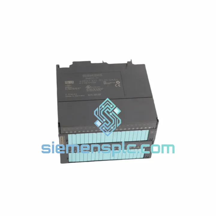
Siemens 6ES7321-1BL00-0AA0 Digital Input Module
SIMATIC
Origin DE
PLC Digital Input Module
Request verified availability, condition, replacement risk review, packing options and courier lead time for 6ES7322-1FL00-0AA0.
Click Request Quote and the part number is inserted into the inquiry form automatically.
Core fields for model confirmation and RFQ routing. Detailed product narrative remains below.
The 6ES7322-1FL00-0AA0 is a high-density digital output module designed for the SIMATIC S7-300 modular PLC platform. It provides 32 transistor-switched sourcing (PNP) output channels, each rated at DC 24V / 0.5A, organized into four galvanically isolated groups of eight channels. Within a distributed or centralized S7-300 rack, this module occupies a single 40mm slot and interfaces directly with the S7-300 backplane bus, receiving process image data from the CPU at every scan cycle without additional gateway hardware. Its role in the control loop is unambiguous: it converts binary output bits from the CPU’s process output image (PAA) into switched DC field signals that actuate solenoid valves, contactors, indicator lamps, relay coils, and solid-state relay inputs across the plant floor.
Real-time Stock & RFQ: [email protected] | WhatsApp: +86 18359268345
| Parameter | Value |
|---|---|
| Order Number (MLFB) | 6ES7322-1FL00-0AA0 |
| Product Family | SIMATIC S7-300 |
| Module Function | Digital Output (DO) |
| Number of Output Channels | 32 |
| Output Voltage (Rated) | DC 24V (18V – 30.2V permissible range) |
| Output Current per Channel | 0.5A continuous |
| Output Type | Transistor, sourcing (PNP) |
| Channel Grouping | 4 groups × 8 channels, each group independently isolated |
| Maximum Aggregate Current per Group | 4A |
| Switching Frequency (Resistive Load) | 100 Hz |
| Switching Frequency (Inductive Load) | 0.5 Hz |
| Output Residual Voltage (ON state) | ≤ 1.2V |
| Leakage Current (OFF state) | ≤ 0.5mA |
| Short-Circuit Protection | Electronic, per channel |
| Isolation Method | Optocoupler (field side ↔ backplane bus) |
| Backplane Bus Interface | S7-300 standard P-bus |
| Module Width | 40mm |
| Dimensions (W × H × D) | 40 × 125 × 120mm |
| Weight | approx. 520g |
| Operating Temperature | 0°C to +60°C (horizontal mounting); 0°C to +40°C (vertical mounting) |
| Storage Temperature | −40°C to +70°C |
| Relative Humidity | 10% – 95%, non-condensing |
| Degree of Protection | IP20 (IEC 60529) |
| Front Connector Required | 6ES7392-1AM00-0AA0 (40-pin screw) or 6ES7392-1BM01-0AA0 (40-pin spring) |
| Certifications | CE, UL 508, cULus, ATEX II 3G (Zone 2), RoHS |
| Warranty | 12 months from date of shipment |
The 6ES7322-1FL00-0AA0 implements a four-stage signal path from backplane bus to field terminal. Understanding each stage is essential for system designers evaluating EMC robustness and fault containment.
Stage 1 — Backplane Bus Reception: The module’s ASIC receives serialized process output image data from the CPU via the S7-300 P-bus at each CPU scan cycle. The P-bus operates at a fixed backplane clock rate; the module latches its 32-bit output word synchronously, ensuring deterministic update timing aligned with the CPU’s output phase. No local microcontroller arbitration is required — the ASIC directly maps the received bit pattern to the 32 output driver enable lines.
Stage 2 — Optocoupler Isolation Barrier: Each of the four channel groups passes through a dedicated optocoupler array. The isolation barrier provides a minimum rated isolation voltage of 500V AC (1 minute test) between the backplane bus potential and the field supply potential. This galvanic separation prevents ground loop currents from the field wiring from coupling noise back into the CPU’s logic supply, a critical requirement in environments with variable-frequency drives (VFDs), large motor contactors, or long cable runs that act as antennas for conducted EMI.
Stage 3 — Transistor Output Driver with Electronic Protection: Each channel uses a discrete PNP power transistor with an integrated protection circuit that monitors output current. When a short-circuit or overload condition is detected (typically at currents exceeding 0.7A–1.0A), the driver enters a current-limiting mode and sets the corresponding diagnostic bit in the module’s status register. This per-channel protection prevents a single wiring fault from propagating thermal stress to adjacent channels or tripping the group fuse. The protection circuit resets automatically once the fault is cleared, without requiring a CPU restart or manual intervention.
Stage 4 — EMC Suppression at Field Terminals: Inductive loads (solenoid valves, relay coils) generate flyback voltage spikes when switched off. The 6ES7322-1FL00-0AA0 does not include internal freewheeling diodes on the output terminals; Siemens engineering guidelines specify that suppression diodes or varistors must be fitted at the load terminals. This design choice is deliberate: external suppression components can be selected to match the specific inductance and switching frequency of each load, providing more precise energy absorption than a fixed internal diode. Engineers must account for this in panel wiring design, particularly for loads with coil inductances above 100mH.
Diagnostic Register Architecture: The module maintains a 4-byte diagnostic data record (DS0) accessible via the CPU’s SFC 51 (RDSYSST) or TIA Portal online diagnostics. Byte 0 contains module-level status flags (supply voltage present, module fault). Bytes 1–4 contain per-group short-circuit flags. This structured diagnostic data enables the CPU program to implement self-healing logic — for example, automatically switching to a redundant output path when a channel fault is detected — without operator intervention.
Every 6ES7322-1FL00-0AA0 unit dispatched from our Xiamen, China facility is a genuine Siemens-manufactured component. Each unit undergoes a structured pre-shipment verification protocol:
Email: [email protected]
WhatsApp: +86 18359268345
Web: siemensplc.com
Location: Xiamen, China
© 2026 siemensplc.com. All rights reserved.
We check the full part number, brand, series and visible nameplate information before quotation.
Sales confirms stock path, condition option, quantity and realistic lead time for export dispatch.
DHL, FedEx, UPS or buyer courier arrangements can be reviewed with packing requirements.
Similar brand or category products for fast comparison and multi-item RFQ lists.