Siemens
RFQ Ready
Siemens A5E03378158 Communication Processor – SIMATIC S7-300 CP 343-1
SIMATIC S7-300
Origin DE
Communication Processor
Request verified availability, condition, replacement risk review, packing options and courier lead time for 6ES7392-1AJ00-0XA0.
Click Request Quote and the part number is inserted into the inquiry form automatically.
Core fields for model confirmation and RFQ routing. Detailed product narrative remains below.
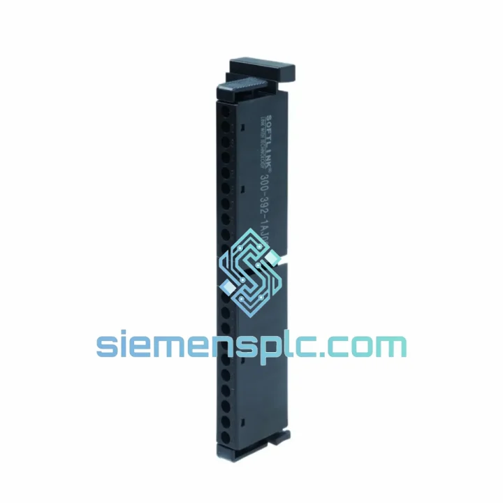
The 6ES7392-1AJ00-0XA0 is the standard 20-pin screw-terminal front connector within the SIMATIC S7-300 accessory portfolio. Its function is structurally non-negotiable: without a correctly seated front connector, no field signal can reach the signal module’s internal I/O circuitry, and the CPU receives no process data from that channel group. In a distributed manufacturing cell or a process skid with dozens of S7-300 I/O racks, a single missing or damaged front connector creates a dead zone that no software workaround can compensate for.
The 6ES7392-1AJ00-0XA0 terminates up to 20 field conductors via individual screw clamps, each rated for wire cross-sections from 0.25 mm² to 1.5 mm² (AWG 24–16). The screw-type clamping mechanism applies a defined torque-controlled contact force that remains stable across thermal cycling — a critical property in panel environments where ambient temperature swings between cold commissioning and full-load operation can exceed 40 °C. Unlike spring-cage alternatives, screw terminals allow field technicians to verify torque with a standard screwdriver and re-tighten without specialized tooling, which is operationally significant in facilities where maintenance personnel rotate frequently.
The connector body is manufactured from a glass-fiber-reinforced thermoplastic rated for continuous operation at 60 °C ambient, with a short-term tolerance to 85 °C. The housing geometry is keyed to the S7-300 signal module face, preventing incorrect insertion orientation. A mechanical coding pin system — adjustable by the installer — allows the connector to be physically coded to a specific module slot, so that during a module swap, an incorrectly typed replacement module cannot be accidentally mated with the wrong wiring harness. This is a hardware-level protection mechanism that operates independently of the CPU’s software configuration.
The integrated cable strain-relief bracket clamps the cable bundle at the connector body, transferring tensile load from the terminal screws to the bracket. This prevents the gradual loosening of screw terminals that occurs when unsupported cable weight creates a persistent downward pull on individual conductors — a failure mode that is common in tall panel installations where cable runs drop vertically from the front connector to the cable duct below.
A labeling strip area on the connector face accepts standard DIN-format terminal markers, enabling systematic identification of each conductor by channel number, signal tag, or P&ID reference. In a 16-channel digital input module, this means each of the 20 terminals (16 signal + 2 common + 2 functional earth) can be individually labeled without ambiguity, reducing wiring errors during commissioning and accelerating fault isolation during maintenance.
Real-time Stock & RFQ: [email protected] | WhatsApp: +86 18359268345
| Parameter | Value |
|---|---|
| Part Number | 6ES7392-1AJ00-0XA0 |
| Series | SIMATIC S7-300 |
| Connector Type | Front Connector, Screw-Type |
| Number of Pins | 20 |
| Terminal Clamping Range | 0.25 mm² – 1.5 mm² (AWG 24–16) |
| Rated Voltage | AC/DC 250 V |
| Rated Current per Terminal | 10 A |
| Contact Resistance | < 5 mΩ (initial, per IEC 60512) |
| Operating Temperature | 0 °C to +60 °C (continuous); –40 °C to +85 °C (storage) |
| Housing Material | Glass-fiber-reinforced thermoplastic (PA66-GF30) |
| Degree of Protection | IP20 (connector body) |
| Vibration Resistance | 10–58 Hz, 0.075 mm amplitude; 58–500 Hz, 1g (IEC 60068-2-6) |
| Shock Resistance | 15g, 11 ms half-sine (IEC 60068-2-27) |
| Compatible Module Pin Count | 20-pin S7-300 signal modules (SM 321, SM 322, SM 331, SM 332, SM 334) |
| Mechanical Coding | Adjustable coding pin, 10 positions |
| Weight | Approx. 120 g |
| Dimensions (W × H × D) | 40 mm × 125 mm × 50 mm |
| Manufacturer | Siemens AG, Germany |
| Warranty | 12 months from date of shipment |
The 6ES7392-1AJ00-0XA0 operates at the physical layer of the S7-300 I/O architecture, but its design decisions have measurable consequences at the system level. Three hardware characteristics are worth detailed examination.
Screw-Terminal Contact Mechanics. Each terminal uses a single-screw clamping design where the screw drives a saddle clamp against the conductor. The saddle geometry distributes clamping force across the conductor cross-section rather than concentrating it at a single point, which reduces the risk of conductor strand damage during tightening. The recommended tightening torque is 0.8 N·m — sufficient to achieve a gas-tight contact interface that resists oxidation ingress. In environments with sulfur-bearing atmospheres (common in chemical plants and wastewater facilities), a gas-tight interface is the primary defense against contact resistance creep, which can introduce millivolt-level offsets in analog signal circuits and trigger nuisance alarms in 4–20 mA loops.
EMC Functional Earth Path. The connector provides two dedicated functional earth (FE) terminals that connect directly to the signal module’s internal shielding bus. When shielded field cables are used — mandatory for analog signals and recommended for high-frequency digital inputs — the cable shield must be terminated at the module, not floated. The FE terminals on the 6ES7392-1AJ00-0XA0 provide this termination point without requiring additional grounding hardware. A properly terminated shield reduces common-mode noise coupling by 20–40 dB in the frequency range of 100 kHz to 10 MHz, which is the primary interference band generated by variable-frequency drives and switching power supplies in the same panel.
Mechanical Coding and Mis-Wiring Prevention. The coding pin system uses a physical key that can be set to one of ten positions. When a front connector is first installed on a module, the installer sets the code. If the module is later replaced with a different module type — for example, a digital output module substituted for a digital input module due to a procurement error — the coding pin prevents the front connector from seating, generating an immediate physical alert before any wiring is energized. This is a deterministic hardware interlock that operates without CPU involvement, making it effective even during power-off maintenance procedures.
Every unit of the 6ES7392-1AJ00-0XA0 supplied by siemensplc.com is a genuine Siemens-manufactured component, sourced through verified supply channels with full part traceability. Each connector is inspected prior to dispatch: terminal screw function, housing integrity, coding pin mechanism, and labeling strip condition are verified against Siemens’ published acceptance criteria. Parts are packed in anti-static, foam-lined cartons to prevent mechanical damage during international transit.
Shipments originate from our warehouse in Xiamen, China, a major export hub with direct access to international freight forwarders serving Europe, Southeast Asia, the Middle East, and the Americas. Standard export documentation — commercial invoice, packing list, and certificate of conformity — is prepared for every order. For orders requiring expedited delivery, DHL Express and FedEx International Priority services are available with typical transit times of 3–5 business days to most destinations. Sea freight consolidation is available for large-volume orders. All shipments are covered by a 12-month warranty from the date of dispatch, covering manufacturing defects and non-conformance to Siemens published specifications.
Email: [email protected]
WhatsApp: +86 18359268345
Web: siemensplc.com
Location: Xiamen, China
© 2026 siemensplc.com. All rights reserved.
{
“@context”: “https://schema.org”,
“@graph”: [
{
“@type”: “Product”,
“name”: “Siemens 6ES7392-1AJ00-0XA0 20-Pin Screw Front Connector for SIMATIC S7-300”,
“description”: “Genuine Siemens 6ES7392-1AJ00-0XA0 20-pin screw-type front connector for SIMATIC S7-300 signal modules. In stock at siemensplc.com, Xiamen, China. Fast global shipping, 12-month warranty.”,
“sku”: “6ES7392-1AJ00-0XA0”,
“mpn”: “6ES7392-1AJ00-0XA0”,
“brand”: {“@type”: “Brand”, “name”: “Siemens”},
“manufacturer”: {“@type”: “Organization”, “name”: “Siemens AG”},
“category”: “PLC Accessories > Front Connectors > SIMATIC S7-300”,
“offers”: {
“@type”: “Offer”,
“seller”: {“@type”: “Organization”, “name”: “siemensplc.com”, “url”: “https://siemensplc.com”},
“availability”: “https://schema.org/InStock”,
“priceCurrency”: “USD”,
“businessFunction”: “https://schema.org/Sell”
}
}
]
}
We check the full part number, brand, series and visible nameplate information before quotation.
Sales confirms stock path, condition option, quantity and realistic lead time for export dispatch.
DHL, FedEx, UPS or buyer courier arrangements can be reviewed with packing requirements.
Similar brand or category products for fast comparison and multi-item RFQ lists.