Siemens
RFQ Ready
Siemens 6GK5786-2HC00-1AA0 Industrial Wireless Access Point
SIMATIC
Origin DE
Industrial Wireless Access Point
Request verified availability, condition, replacement risk review, packing options and courier lead time for 6ES7972-0BB12-0XA0.
Click Request Quote and the part number is inserted into the inquiry form automatically.
Core fields for model confirmation and RFQ routing. Detailed product narrative remains below.
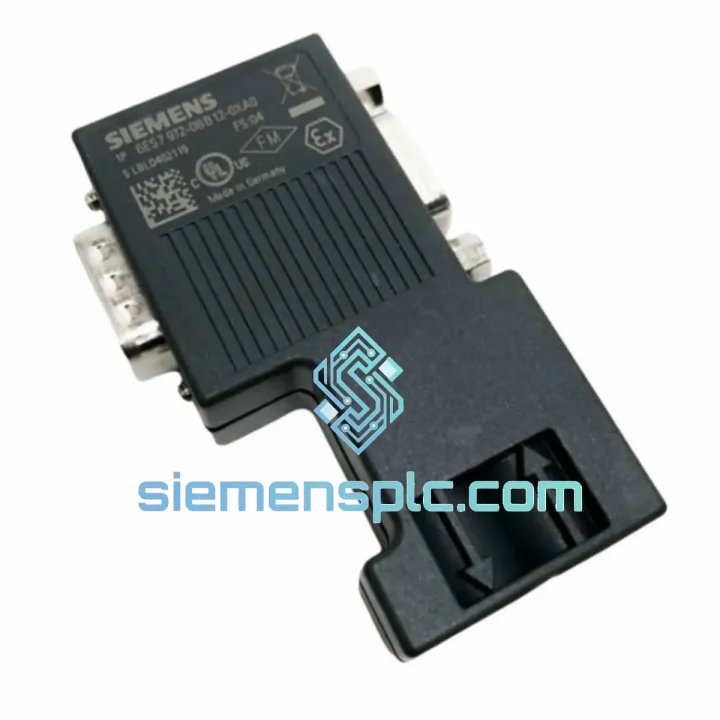
The 6ES7972-0BB12-0XA0 is a 9-pin Sub-D PROFIBUS DP bus connector manufactured by Siemens AG for use within the SIMATIC S7 automation platform. It provides a mechanically and electrically compliant interface between PROFIBUS DP cables and the DP port of any SIMATIC CPU, CP, or distributed I/O station. The 90° axial cable exit geometry is specifically engineered for installations where panel depth is constrained, allowing the cable to route parallel to the mounting surface immediately after the connector body rather than projecting outward. This geometry reduces the minimum bending radius stress on the cable jacket and simplifies cable tray routing in densely populated control cabinets.
Within a PROFIBUS DP segment, every physical node — whether a master CPU or a slave I/O station — requires a mechanically sound, impedance-matched connection to the twisted-pair bus cable. The 6ES7972-0BB12-0XA0 fulfils this role with an on-board switchable termination network (two 390 Ω resistors and one 220 Ω resistor in the standard RS-485 termination topology), which must be activated only at the two physical endpoints of each segment. Incorrect termination is one of the most common root causes of PROFIBUS communication errors at baud rates above 1.5 Mbit/s; the clearly marked slide switch on this connector eliminates ambiguity during commissioning and maintenance.
The connector is rated for the full PROFIBUS DP baud-rate range from 9.6 kbit/s up to 12 Mbit/s. At 12 Mbit/s, the maximum permissible segment length drops to 100 m per IEC 61158-2, and signal integrity becomes highly sensitive to connector contact resistance and impedance discontinuities. Siemens specifies the contact resistance of this connector at less than 30 mΩ per pin, which keeps the voltage drop across the connector negligible relative to the RS-485 differential signal swing of nominally ±200 mV at the receiver threshold.
The housing is constructed from a glass-fibre-reinforced thermoplastic compound with a UL 94 V-0 flammability rating. The Sub-D shell is zinc die-cast, providing both mechanical rigidity and a continuous EMC shielding path from the cable braid through the connector body to the device chassis ground when the cable shield is correctly terminated at the connector’s PG screw clamp. This shielding continuity is critical in environments with high-frequency switching noise from variable-frequency drives (VFDs) or servo amplifiers operating in the same cabinet.
Siemensplc.com maintains verified stock of the 6ES7972-0BB12-0XA0 and ships from Xiamen, China, with same-day dispatch on orders confirmed before 14:00 CST. All units carry a 12-month warranty against manufacturing defects.
Real-time Stock & RFQ: [email protected] | WhatsApp: +86 18359268345
| Parameter | Value |
|---|---|
| Siemens Order Number | 6ES7972-0BB12-0XA0 |
| Product Family | SIMATIC S7 / PROFIBUS DP |
| Interface Standard | PROFIBUS DP per IEC 61158 / EN 50170 |
| Physical Layer | RS-485, balanced differential pair |
| Connector Type | 9-pin Sub-D (DB9), female on device side |
| Cable Exit Angle | 90° axial |
| Supported Baud Rates | 9.6 kbit/s – 12 Mbit/s (all standard PROFIBUS rates) |
| Bus Termination | Switchable on-board (390 Ω / 220 Ω / 390 Ω network) |
| Contact Resistance | < 30 mΩ per pin |
| Cable Conductor Cross-Section | 0.22 mm² (AWG 24) recommended; 0.34 mm² max |
| Operating Temperature | −20 °C to +85 °C |
| Storage Temperature | −40 °C to +85 °C |
| Protection Class | IP20 (connector body) |
| Housing Material | GF-reinforced thermoplastic, UL 94 V-0 |
| Shell Material | Zinc die-cast (EMC shielding) |
| Locking Mechanism | Metric M3 locking screws, captive |
| Compliance | CE, RoHS 2011/65/EU, REACH |
| Country of Origin | Germany |
| Warranty | 12 months from date of shipment |
The RS-485 physical layer used by PROFIBUS DP relies on differential signalling across a 120 Ω characteristic-impedance twisted-pair cable. Any impedance discontinuity along the segment — including at connector interfaces — generates a reflected wave that superimposes on the forward-travelling signal. At 12 Mbit/s, the bit period is approximately 83 ns; a reflection with a round-trip delay exceeding 20 ns (corresponding to roughly 2 m of cable) can corrupt the trailing edge of a bit cell. The 6ES7972-0BB12-0XA0 addresses this through a compact, low-inductance internal wiring layout that minimises the electrical length of the signal path through the connector body, keeping parasitic inductance below 10 nH per signal pin.
The on-board termination network deserves specific attention. The standard RS-485 termination topology requires a pull-up resistor from the A-line to +5 V, a pull-down resistor from the B-line to GND, and a termination resistor across A and B. In this connector, the pull-up and pull-down resistors (390 Ω each) are connected to the VP (+5 V) and DGND pins of the Sub-D connector, which are supplied by the PROFIBUS master or the first slave in the segment. The termination resistor (220 Ω) bridges the A and B lines. When the slide switch is in the ON position, this network is inserted; when OFF, the network is disconnected and the connector acts as a transparent pass-through node. This design means the termination power is drawn from the bus itself, eliminating the need for an external power supply at the segment endpoint — a significant advantage in field installations where auxiliary 5 V rails are not available at every cabinet.
EMC performance is achieved through the zinc die-cast shell, which provides a Faraday cage around the signal pins. The cable shield clamp inside the connector body makes a 360° circumferential contact with the cable braid when the PG screw is tightened, ensuring the shield is grounded at the connector rather than relying on a pigtail connection. Pigtail shield terminations introduce inductance that degrades high-frequency shielding effectiveness above approximately 1 MHz — the 360° clamp maintains low-impedance shielding continuity up to the GHz range, well beyond the spectral content of a 12 Mbit/s PROFIBUS signal.
The M3 locking screws on the Sub-D shell provide a measured insertion retention force that prevents accidental disconnection under vibration loads consistent with IEC 60068-2-6 (sinusoidal vibration, 10–150 Hz, 1 g). This is particularly relevant in machine tool and press applications where the control cabinet is subject to continuous low-frequency vibration from the machine structure.
Every 6ES7972-0BB12-0XA0 unit supplied by siemensplc.com is sourced through verified industrial distribution channels with full chain-of-custody traceability back to Siemens AG manufacturing. Units are physically inspected upon receipt for label authenticity, housing integrity, pin condition, and correct part-number markings. Batch samples undergo electrical continuity testing and termination-resistor switching verification before warehousing. Each shipment includes a 12-month warranty certificate valid from the date of dispatch.
Our warehouse is located in Xiamen, China — a major export hub with direct access to DHL Express, FedEx International Priority, and UPS Worldwide services. Orders confirmed before 14:00 CST are dispatched same day. Typical transit times are 3–5 business days to Europe, 4–6 business days to North America, and 2–4 business days to Southeast Asia. Export documentation — commercial invoice, packing list, certificate of origin, and Siemens product datasheet — is provided with every international shipment. Volume pricing is available for orders of 10 or more units; contact us with your BOM for a formal quotation within 24 hours.
Email: [email protected]
WhatsApp: +86 18359268345
Web: siemensplc.com
Location: Xiamen, China
© 2026 siemensplc.com. All rights reserved.
We check the full part number, brand, series and visible nameplate information before quotation.
Sales confirms stock path, condition option, quantity and realistic lead time for export dispatch.
DHL, FedEx, UPS or buyer courier arrangements can be reviewed with packing requirements.
Similar brand or category products for fast comparison and multi-item RFQ lists.