Siemens
RFQ Ready
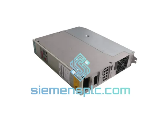
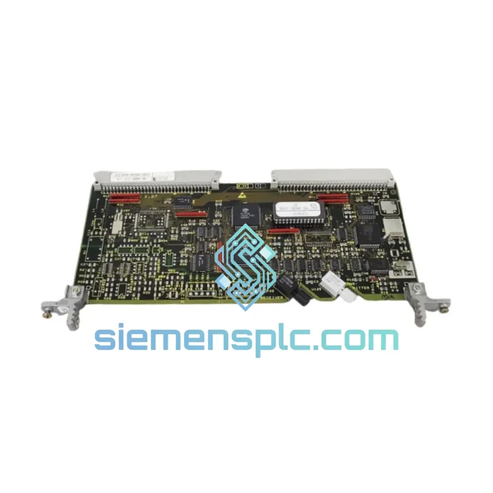
Siemens 6SE7031-7HG84-1JA1 Power Supply Module
SIMOVERT
Origin DE
PLC Power Supply Module
Request verified availability, condition, replacement risk review, packing options and courier lead time for 6SE7090-0XX84-0BC0.
Click Request Quote and the part number is inserted into the inquiry form automatically.
Core fields for model confirmation and RFQ routing. Detailed product narrative remains below.
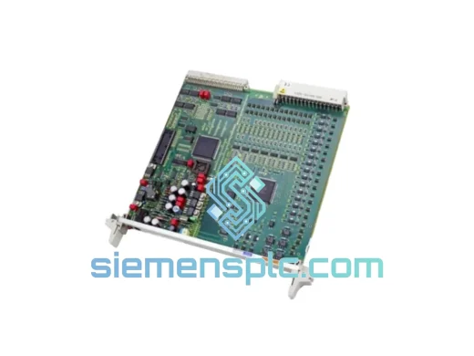
The 6SE7090-0XX84-0BC0 is the SCB1 (Serial Communication Board 1) option module for the Siemens SIMOVERT MASTERDRIVES 6SE70 series variable-speed drives. Its primary function within a drive control loop is to provide galvanically isolated, high-immunity serial data exchange between the drive’s internal control unit and external automation systems or peer drives — without the signal degradation and ground-loop interference that copper-based RS-485 links introduce in heavy industrial environments.
The board occupies one option slot (C or D) on the MASTERDRIVES chassis and communicates with the Control Unit (CU) via the internal option-slot bus, operating at the drive’s internal cycle time. This tight coupling means process data (PZD) and parameter data (PKW) are exchanged within the drive’s own task scheduler, preserving deterministic timing across the entire control chain. For multi-drive applications — coordinated winders, draw-roll sections, or synchronised hoists — this determinism is not optional; it is the architectural foundation of the system.
The fiber optic physical layer eliminates common-mode voltage problems that arise when drives share a DC bus or when cable runs cross high-potential zones such as transformer bays or welding stations. Optical fiber carries no conducted emissions and is immune to radiated fields up to the limits defined in EN 61800-3 Category C3. This makes the SCB1 the correct engineering choice wherever EMC compliance must be maintained without relying on expensive shielded copper infrastructure.
The board supports peer-to-peer (P2P) fiber optic ring topology, allowing up to 12 drives to be linked in a closed ring with a single master. Each node receives and retransmits the optical signal, so cable length between nodes can reach 10 m (plastic optical fiber, POF) or up to 300 m with glass fiber (GOF) — enabling drive networks that span large machine halls without signal repeaters. The ring topology also provides inherent fault detection: a broken fiber segment is immediately visible to the master as a loss-of-synchronisation fault, enabling rapid maintenance response.
In USS protocol mode, the SCB1 interfaces with Siemens SIMATIC S7 PLCs, HMIs, or third-party controllers via the fiber optic link, using the standard USS telegram structure (STW/ZSW, HSW/HIW). Parameter access follows the PKW mechanism defined in the MASTERDRIVES parameter manual, giving the host controller full read/write access to all drive parameters without interrupting the process data channel. This dual-channel architecture — simultaneous PZD and PKW — is essential for drives that must maintain speed control while a SCADA system reads diagnostic data in the background.
Real-time Stock & RFQ: [email protected] | WhatsApp: +86 18359268345
| Parameter | Value |
|---|---|
| Part Number | 6SE7090-0XX84-0BC0 |
| Board Designation | SCB1 — Serial Communication Board 1 |
| Compatible Drive Series | SIMOVERT MASTERDRIVES 6SE70 (VC / MC / FC chassis) |
| Mounting Location | Option slot C or D on MASTERDRIVES chassis |
| Physical Layer | Fiber optic — POF (plastic) or GOF (glass) |
| Max. POF Segment Length | 10 m (HFBR-type connectors) |
| Max. GOF Segment Length | 300 m (ST connectors) |
| Max. Nodes per Ring | 12 drives |
| Supported Protocols | Peer-to-Peer (P2P), USS over fiber optic |
| Data Exchange Channels | PZD (process data) + PKW (parameter data), simultaneous |
| Internal Bus Interface | MASTERDRIVES option-slot bus (CU-side) |
| Operating Temperature | 0 °C to +55 °C (storage: −25 °C to +70 °C) |
| Relative Humidity | 5 % to 95 %, non-condensing (Class 3K3 per EN 60721-3-3) |
| Supply Voltage | Powered from drive option-slot bus (no external supply required) |
| EMC Immunity | EN 61800-3 Category C3 (industrial environment) |
| Certifications | CE (LVD + EMC Directive), UL Recognized, RoHS compliant |
| Manufacturer | Siemens AG, Germany |
| Country of Origin | Germany |
| Warranty | 12 months against manufacturing defects |
The SCB1’s hardware architecture addresses three distinct engineering problems: galvanic isolation, signal integrity over distance, and deterministic data delivery.
Galvanic Isolation via Optical Transceiver Stage. The board’s transmit and receive paths are built around HFBR-series (or equivalent) optical transceivers. The electrical-to-optical conversion occurs at the board boundary, meaning no conductive path exists between the drive’s internal logic ground and the fiber cable plant. This eliminates the ground potential difference (GPD) problem that affects copper RS-485 links when drives are fed from separate transformer secondaries or when cable shields are grounded at both ends. In a steel mill or press shop where GPD can reach tens of volts, this isolation is not a convenience — it is a protection mechanism for both the board and the connected controller.
Ring Topology and Signal Regeneration. Each SCB1 node in a P2P ring receives the incoming optical signal, decodes it to digital logic, re-encodes it, and retransmits a fresh optical pulse to the next node. This active regeneration means the signal quality at node 12 is identical to node 1 — there is no cumulative attenuation or jitter accumulation as seen in passive electrical bus topologies. The ring master detects synchronisation loss within one communication cycle, providing sub-millisecond fault detection latency.
EMC Design and PCB Layout. The board uses a multi-layer PCB with dedicated ground planes separating the optical transceiver section from the option-slot bus interface. Decoupling capacitors are placed at each power rail entry point, and the option-slot connector pins are filtered to suppress high-frequency noise conducted from the drive’s power stage. This layout follows Siemens’ internal EMC design rules for drive option boards, which are validated against EN 55011 Class A conducted and radiated emission limits.
Option-Slot Bus Protocol Handling. The SCB1’s ASIC or FPGA logic manages the handshake with the CU’s option-slot bus, which operates synchronously with the drive’s current controller cycle (typically 600 µs or 1.2 ms depending on the CU variant). PZD words are latched at the start of each cycle and presented to the CU’s parameter processor without additional buffering delay. This zero-added-latency architecture is what makes the SCB1 suitable for closed-loop tension control in winder applications, where a one-cycle delay in speed reference delivery would introduce measurable tension ripple.
Every 6SE7090-0XX84-0BC0 unit supplied by siemensplc.com is sourced as genuine Siemens AG manufactured hardware. Authenticity verification covers three checkpoints: factory label integrity (Siemens holographic security label, date code, and revision suffix), PCB marking cross-reference against Siemens internal part documentation, and physical connector condition inspection under magnification.
Units are stored in ESD-controlled conditions (relative humidity 40–60 %, temperature 18–25 °C) in our Xiamen, China warehouse. Prior to dispatch, each board is individually wrapped in anti-static shielding bags, placed in foam-lined inner cartons, and sealed in double-wall corrugated outer packaging rated for international air freight handling. Fragile and ESD-sensitive markings are applied to all outer surfaces.
Shipping is handled via DHL Express, FedEx International Priority, or UPS Worldwide Expedited from Xiamen Gaoqi International Airport (XMN). In-stock units are dispatched within 1 business day of payment confirmation. Transit times to major destinations: Europe 3–5 days, North America 3–4 days, Southeast Asia 2–3 days, Middle East 4–6 days. Commercial invoice, packing list, and certificate of origin are included with every shipment. HS code 8537.10 documentation is provided for customs clearance.
A 12-month warranty covers manufacturing defects under normal operating conditions. DOA units are replaced within 5 business days of confirmed fault report. Warranty claims are processed via email with photographic evidence; no return-to-origin required for DOA cases on orders of single units.
Email: [email protected]
WhatsApp: +86 18359268345
Web: siemensplc.com
Location: Xiamen, China
© 2026 siemensplc.com. All rights reserved.
We check the full part number, brand, series and visible nameplate information before quotation.
Sales confirms stock path, condition option, quantity and realistic lead time for export dispatch.
DHL, FedEx, UPS or buyer courier arrangements can be reviewed with packing requirements.
Similar brand or category products for fast comparison and multi-item RFQ lists.