Siemens
RFQ Ready
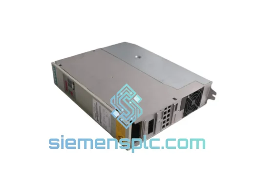
Siemens 6SE7031-7HG84-1JA1 Power Supply Module
SIMOVERT
Origin DE
PLC Power Supply Module
Request verified availability, condition, replacement risk review, packing options and courier lead time for 6SE7090-0XX84-6AB5.
Click Request Quote and the part number is inserted into the inquiry form automatically.
Core fields for model confirmation and RFQ routing. Detailed product narrative remains below.
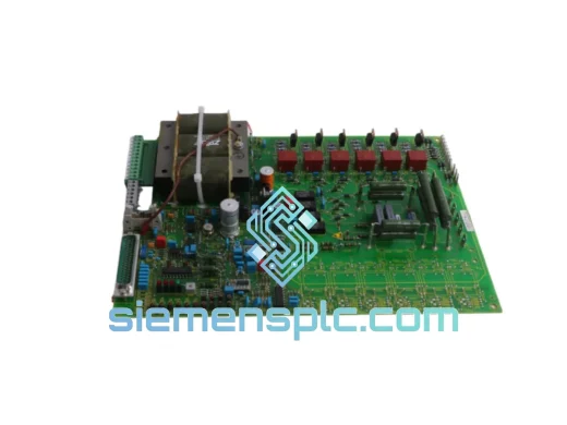
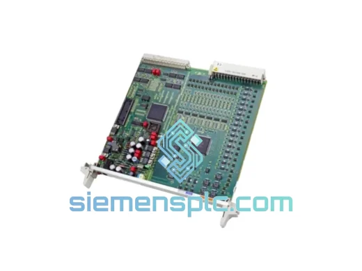
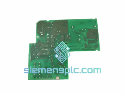
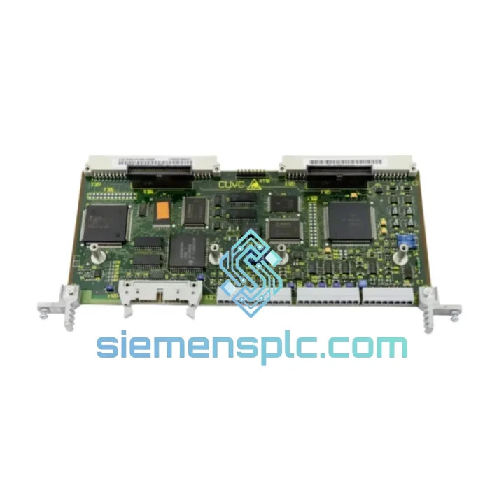
The Siemens 6SE7090-0XX84-6AB5 is the central interface and signal-routing board within the SIMOVERT MASTERDRIVES drive family — a platform that spans MC (Motion Control), VC (Vector Control), and FC (Frequency Control) topologies. Its primary function is to bridge the drive’s control unit (CU) and the power section (inverter stack), managing the bidirectional exchange of PWM gate signals, encoder feedback, fault status bits, and DC-link voltage measurements across the internal drive bus at deterministic cycle times.
In a closed-loop vector-controlled drive, the interface board is not a passive connector assembly. It performs active signal conditioning: differential line receivers on the encoder input channels reject common-mode noise up to ±15 V, while optocoupler stages on the gate-drive outputs enforce a minimum 2.5 kV isolation barrier between the low-voltage control domain and the high-voltage IGBT gate domain. The board also hosts the DC-link voltage measurement divider network, whose precision resistor chain (tolerance ≤ 0.1%) feeds the ADC on the control unit — a direct input to the DC-bus overvoltage protection algorithm.
For procurement engineers and maintenance teams managing SIMOVERT MASTERDRIVES installations in steel mills, paper lines, chemical plants, or crane systems, the 6SE7090-0XX84-6AB5 represents a field-replaceable unit (FRU) that restores full drive functionality without requiring control unit or power module replacement. Stocking this board as a critical spare reduces mean time to repair (MTTR) from days to under two hours in most configurations.
Real-time Stock & RFQ: [email protected] | WhatsApp: +86 18359268345
| Parameter | Value / Specification |
|---|---|
| Manufacturer | Siemens AG |
| Part Number (SKU) | 6SE7090-0XX84-6AB5 |
| Product Series | SIMOVERT MASTERDRIVES (MC / VC / FC) |
| Component Classification | Interface / Drive Board (FRU) |
| Isolation Voltage (Gate Drive) | ≥ 2,500 V (optocoupler stage) |
| Encoder Input Common-Mode Rejection | ±15 V (differential line receiver) |
| DC-Link Voltage Divider Tolerance | ≤ 0.1% (precision resistor network) |
| Operating Temperature Range | 0 °C to +55 °C (ambient, forced-air cooled) |
| Storage Temperature | −25 °C to +70 °C |
| Relative Humidity | 5% to 95%, non-condensing |
| Vibration Resistance | IEC 60068-2-6 (10–150 Hz, 1 g) |
| Shock Resistance | IEC 60068-2-27 (15 g, 11 ms) |
| EMC Compliance | EN 61800-3 Category C2 |
| Weight | Approx. 2,300 g |
| Country of Origin | Germany |
| Warranty | 12 months from date of shipment |
The 6SE7090-0XX84-6AB5 board architecture reflects the design philosophy of the SIMOVERT MASTERDRIVES platform: deterministic signal paths, layered isolation, and hardware-enforced fault containment.
Optocoupler Isolation Architecture: Each PWM gate-drive channel passes through a dedicated high-speed optocoupler (propagation delay ≤ 500 ns) before reaching the IGBT gate resistor network. This arrangement ensures that a fault event in the power section — including a phase-to-phase short — cannot propagate back into the control unit’s logic domain. The isolation barrier is rated at 2,500 V continuous, exceeding the IEC 61800-5-1 reinforced insulation requirement for 690 V drive systems.
Encoder Feedback Signal Conditioning: The board accepts HTL (High Threshold Logic) and TTL incremental encoder signals on its feedback input terminals. RS-422 differential line receivers provide ±15 V common-mode rejection, which is essential in environments with heavy motor cabling running parallel to encoder wiring. A hardware filter stage (RC low-pass, fc ≈ 200 kHz) suppresses high-frequency conducted noise before the signal reaches the control unit’s position counter, preventing false edge counts that would corrupt speed feedback in closed-loop vector control.
DC-Link Measurement Network: A precision voltage divider — constructed from metal-film resistors with ±0.1% tolerance and ≤ 15 ppm/°C temperature coefficient — scales the DC-link voltage (typically 540–750 V DC for 400 V AC input) down to the ADC input range of the control unit. The low temperature coefficient ensures that the overvoltage trip threshold remains accurate across the full operating temperature range, preventing nuisance trips in high-ambient installations.
EMC Design: The board layout follows a split-ground plane strategy: the analog measurement ground, digital logic ground, and chassis ground are connected at a single star point adjacent to the board’s mounting bracket. This topology minimizes circulating ground currents induced by the switching IGBT stack, which generates common-mode voltage transients of several hundred volts per microsecond (dV/dt). Ferrite beads on the signal lines between the board and the control unit further attenuate high-frequency conducted emissions.
Fault Latch and Status Reporting: Hardware fault latches on the board capture overcurrent, overvoltage, and gate-drive undervoltage events at the hardware level — independent of the control unit’s firmware scan cycle. The latched fault status is transmitted to the control unit via the internal drive bus within one PWM period (typically 200–400 µs at standard switching frequencies), enabling the control unit to initiate a controlled stop sequence before the fault propagates to a hard trip.
Every Siemens 6SE7090-0XX84-6AB5 unit supplied by siemensplc.com is sourced as genuine Siemens OEM hardware. Each board undergoes a pre-shipment inspection protocol that includes visual examination for physical damage, ESD compliance verification, and functional continuity checks on isolation barriers and signal paths. Units are packed in anti-static shielding bags with humidity indicator cards, placed in foam-lined cartons rated for IEC 60068-2-27 shock conditions, and sealed with tamper-evident tape.
Shipments originate from our warehouse in Xiamen, China — a major logistics hub with direct access to international express carriers (DHL, FedEx, UPS) and sea freight consolidators. Standard express delivery to Europe, Southeast Asia, and the Middle East is 3–5 business days. North America and Australia typically receive shipments within 5–7 business days. All shipments include a commercial invoice, packing list, and certificate of origin. Customs HS code documentation is provided upon request to facilitate import clearance.
A 12-month warranty covers all units against manufacturing defects and premature failure under normal operating conditions. Warranty claims are processed within 5 business days of receipt of the returned unit, with replacement dispatch on the same day as claim approval.
Email: [email protected]
WhatsApp: +86 18359268345
Web: siemensplc.com
Location: Xiamen, China
© 2026 siemensplc.com. All rights reserved.
We check the full part number, brand, series and visible nameplate information before quotation.
Sales confirms stock path, condition option, quantity and realistic lead time for export dispatch.
DHL, FedEx, UPS or buyer courier arrangements can be reviewed with packing requirements.
Similar brand or category products for fast comparison and multi-item RFQ lists.