Siemens
RFQ Ready
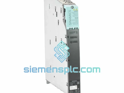
Siemens 6SL3210-1KE18-8UP1 AC Drive Power Module
SINAMICS
Origin DE
AC Drive Power Module
Request verified availability, condition, replacement risk review, packing options and courier lead time for 6SL3210-1SE31-1UA0.
Click Request Quote and the part number is inserted into the inquiry form automatically.
Core fields for model confirmation and RFQ routing. Detailed product narrative remains below.
The Siemens 6SL3210-1SE31-1UA0 is a single-axis PM340 Power Module in the SINAMICS S120 booksize format, rated at 11 kW continuous output power on a 3-phase AC 380–480 V supply. Within the S120 system topology, the PM340 occupies the power conversion layer between the DC bus — fed by a Line Module — and the connected AC motor. It does not carry an independent rectifier stage; instead, it draws regulated DC from the shared bus and inverts it to variable-frequency, variable-voltage AC via a three-phase IGBT bridge. This architecture separates the rectification function from the inversion function, which is the defining characteristic of the S120 booksize platform and the basis for its energy-sharing capability across axes.
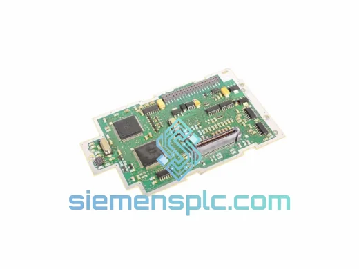
The module interfaces with a CU320-2 or CU310-2 Control Unit exclusively through DRIVE-CLiQ — Siemens’ proprietary serial communication interface operating at 100 Mbit/s over a standardized RJ45-style connector. DRIVE-CLiQ carries both control data (setpoints, actual values, fault codes) and device identification data (electronic nameplate), eliminating manual parameter entry for motor and encoder configuration. The PM340 stores its own electronic nameplate in onboard EEPROM, which the Control Unit reads at startup to auto-configure the drive topology without operator intervention.
In multi-axis cabinet installations, the 60 mm booksize width allows dense packing of multiple PM340 units on a shared DC bus rail. A single Active Line Module (ALM) can supply several PM340 axes simultaneously, and regenerative energy from decelerating axes is redistributed across the bus to motoring axes in real time — reducing peak grid demand and eliminating the need for braking resistors in balanced load profiles. For single-axis or unbalanced configurations, an external braking resistor connected to the PM340’s braking chopper terminal handles excess regenerative energy.
The 6SL3210-1SE31-1UA0 supports a default pulse frequency of 4 kHz, adjustable up to 16 kHz for low-noise motor operation or high-bandwidth current control loops. At elevated pulse frequencies, output current must be derated per the Siemens derating curves in the S120 Hardware Installation Manual (document A5E03263479). The onboard gate driver circuitry uses desaturation detection on each IGBT to identify short-circuit conditions within 2–3 µs, triggering a hardware-level shutdown before the Control Unit’s software fault response activates — a two-layer protection mechanism that preserves both the module and the connected motor winding.
Safe Torque Off (STO) is implemented at the hardware level via dual-channel 24 V DC inputs on the PM340’s terminal strip. When STO is activated, the gate driver supply to the IGBT bridge is interrupted by two independent hardware paths, preventing any torque-generating current from flowing to the motor. This implementation meets IEC 62061 SIL 2 and EN ISO 13849-1 PLd without requiring an external safety relay for the STO function itself. The SS1 (Safe Stop 1) function, which ramps the drive to zero speed before activating STO, is coordinated by the Control Unit’s F-capable firmware in conjunction with a Siemens F-CPU over PROFIsafe.
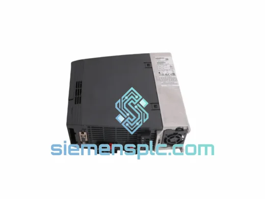
Thermal management relies on a forced-air cooling system with an internal fan drawing air from the bottom of the module and exhausting from the top — consistent with the standard S120 booksize airflow direction. The module is rated for ambient temperatures from 0 °C to +40 °C at full rated current, with linear derating to +55 °C. An NTC thermistor mounted on the IGBT heatsink feeds temperature data to the Control Unit via DRIVE-CLiQ, enabling predictive thermal derating before an overtemperature fault (F30024) occurs. This thermal transparency is a key diagnostic advantage in high-ambient industrial environments.
Real-time Stock & RFQ: [email protected] | WhatsApp: +86 18359268345
| Order Number (MLFB) | 6SL3210-1SE31-1UA0 |
| Platform | SINAMICS S120 Booksize |
| Module Function | PM340 Single-Axis Power Module (Inverter Stage Only) |
| Rated Output Power | 11 kW (at 400 V AC, 40 °C ambient) |
| Input Voltage Range | 3 AC 380 – 480 V ±10% |
| Input Frequency | 47 – 63 Hz |
| Rated Output Current | 25 A (continuous) |
| Peak Output Current | 37.5 A (150% for 60 s); 50 A (200% for 3 s) |
| DC Bus Voltage | 510 – 720 V DC (from Line Module) |
| Default Pulse Frequency | 4 kHz (adjustable to 16 kHz with derating) |
| Control Interface | DRIVE-CLiQ (100 Mbit/s, RJ45) |
| STO Safety Function | Dual-channel hardware STO, SIL 2 / PLd |
| Protection Class | IP20 |
| Cooling | Forced air, bottom-to-top airflow, internal fan |
| Ambient Temperature (Operation) | 0 °C to +40 °C (derated to +55 °C) |
| Storage Temperature | -40 °C to +70 °C |
| Relative Humidity | ≤ 95% RH, non-condensing |
| Installation Altitude | ≤ 1000 m ASL (derated above) |
| Dimensions (H × W × D) | 380 × 60 × 270 mm |
| Weight | approx. 5.07 kg |
| Certifications | CE, UL, cUL, RoHS 2 |
| Country of Origin | Germany |
| HS Code | 8504409990 |
| Warranty | 12 months — manufacturing defects; DOA replacement within 7 business days |
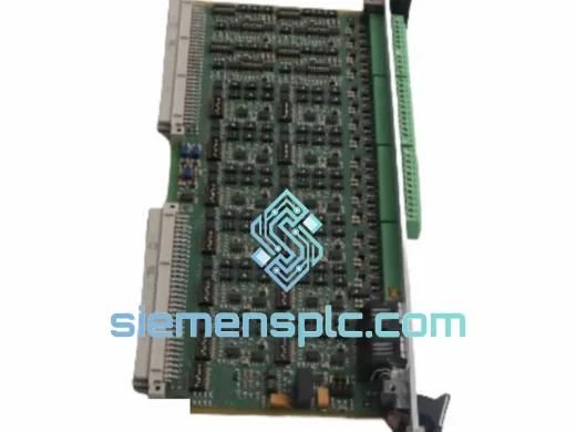
IGBT Bridge Architecture: The PM340 uses a three-phase, two-level IGBT inverter bridge. Each of the six IGBT positions is driven by an isolated gate driver with desaturation detection. Under a short-circuit event, the collector-emitter voltage rises above the desaturation threshold within 2–3 µs, triggering a controlled soft-shutdown sequence that limits di/dt and suppresses voltage spikes on the DC bus — protecting both the IGBT junction and the motor winding insulation.
EMC Design: The booksize housing integrates a Class C2 EMC filter on the DC bus input side, suppressing conducted emissions in the 150 kHz – 30 MHz band per EN 61800-3. The PCB layout routes high-current switching paths on inner copper layers with ground planes on outer layers, minimizing loop area and radiated emissions. Shielded DRIVE-CLiQ cables are mandatory for compliance; the module’s DRIVE-CLiQ port includes common-mode choke termination to suppress cable-coupled noise.
Thermal Monitoring: An NTC thermistor bonded directly to the IGBT heatsink provides continuous junction-temperature-correlated feedback to the Control Unit. The firmware implements a two-stage thermal response: at 80% of the maximum heatsink temperature, the pulse frequency is automatically reduced from the set value to 4 kHz to lower switching losses; at 100%, output current is derated linearly. This graduated response prevents abrupt fault trips during thermal transients in high-ambient environments.
DC Bus Capacitor Bank: The PM340 contains a DC link capacitor bank sized for the 11 kW power class. These capacitors buffer energy during commutation and absorb voltage ripple from the shared bus. The capacitor bank’s equivalent series resistance (ESR) and capacitance are monitored indirectly via DC bus voltage ripple analysis in the Control Unit firmware — a degradation indicator that appears in the drive’s diagnostic data before capacitor failure causes a bus overvoltage fault (F30002).
Braking Chopper: An integrated braking chopper IGBT connects to an external braking resistor terminal. The chopper activates when DC bus voltage exceeds approximately 780 V DC (for 480 V input systems), dissipating excess regenerative energy as heat in the external resistor. The chopper duty cycle is controlled by the firmware to maintain bus voltage within the operating window, with a hardware overvoltage clamp as a secondary protection layer.
Every 6SL3210-1SE31-1UA0 unit supplied by siemensplc.com is sourced through verified Siemens distribution channels and authorized OEM surplus stock. Before dispatch from our Xiamen, China facility, each module undergoes a structured inspection protocol: visual examination of housing, label authenticity verification (holographic seal, laser-engraved serial number cross-referenced against Siemens’ product traceability database), and a functional power-on test confirming DRIVE-CLiQ enumeration and STO channel continuity.
Units ship in original Siemens ESD-safe packaging — foam-lined cardboard with anti-static inner bag — preserving the module’s electrostatic discharge immunity rating during transit. Export documentation includes a commercial invoice, packing list, EU Declaration of Conformity, and test report. Customs HS code 8504409990 is pre-declared on all shipments to minimize clearance delays.
Logistics partners include DHL Express and FedEx International Priority, with typical transit times of 3–5 business days to Europe and North America, and 2–4 business days to Southeast Asia. Full shipment tracking is provided at order confirmation. For time-critical plant shutdowns, same-day dispatch is available for in-stock units ordered before 14:00 CST.
A 12-month warranty covers manufacturing defects from the date of delivery. Dead-on-arrival (DOA) units are replaced within 7 business days of confirmed fault report. Post-delivery technical support — including Startdrive commissioning guidance, parameter file templates, and DRIVE-CLiQ topology troubleshooting — is available at no additional charge via email or WhatsApp.
Email: [email protected]
WhatsApp: +86 18359268345
Web: siemensplc.com
Location: Xiamen, China
© 2026 siemensplc.com. All rights reserved.
We check the full part number, brand, series and visible nameplate information before quotation.
Sales confirms stock path, condition option, quantity and realistic lead time for export dispatch.
DHL, FedEx, UPS or buyer courier arrangements can be reviewed with packing requirements.
Similar brand or category products for fast comparison and multi-item RFQ lists.