Siemens
In Stock OK
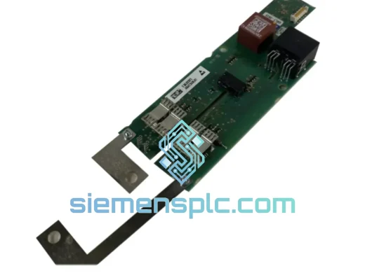
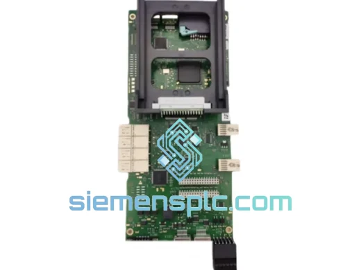
Siemens A1A10000423.00M I/O Interface Board – Robicon Perfect Harmony
Request verified availability, condition, replacement risk review, packing options and courier lead time for A1A10000423.00M.
BrandSiemens
Part NumberA1A10000423.00M
ConditionAvailability Check
Lead TimeRFQ Confirmation
DocumentsDatasheet / photos by RFQ
ShippingExport packing available
Auto-filled RFQ
A1A10000423.00M
Click Request Quote and the part number is inserted into the inquiry form automatically.
- Reply by email: [email protected]
- WhatsApp / Tel: +86 18359268345
- Mon-Sat 9:00-18:00 GMT+8
Procurement Data
Key Product Information
Core fields for model confirmation and RFQ routing. Detailed product narrative remains below.
- Brand
- Siemens
- Primary Part Number
- A1A10000423.00M
- Product Type
- I/O Interface Board
- Product Family
- Other series
- Manufacturer
- Siemens AG (Robicon Division)
- Country of Origin
- DE
- Catalog Category
- I/O Modules
- Operating Temp.
- 0 °C to +55 °C (ambient, within drive enclosure)
- Warranty
- 12 months from date of shipment
Model confirmed for inquiry
A1A10000423.00M
Send quantity, destination and urgency. The RFQ form keeps this part number attached.
Request Quote
Product Overview
Siemens A1A10000423.00M I/O Interface Board: Signal Arbitration Core of the Robicon Perfect Harmony MV Drive
The Siemens A1A10000423.00M is the dedicated I/O interface board installed within the Robicon Perfect Harmony medium voltage variable frequency drive (MV VFD) platform. Its function is not peripheral — it occupies the signal boundary between the drive’s central control logic and the field instrumentation layer. Every process feedback signal, every digital command, and every analog reference that enters or exits the drive’s control architecture passes through this board’s conditioning and isolation circuitry. When this board fails, the drive loses situational awareness: speed references become undefined, fault signals go undetected, and the control loop collapses. In continuous-process industries where a single MV drive may govern a 3,000 kW boiler feed pump or a 6 kV compressor train, that failure mode is operationally unacceptable.
The Perfect Harmony platform — originally developed by Robicon Corporation and subsequently integrated into Siemens’ drive portfolio — uses a cascaded H-bridge power cell architecture operating at medium voltage (typically 2.3 kV to 13.8 kV). The A1A10000423.00M board is engineered to operate reliably within the electromagnetic environment generated by this topology, where high dV/dt switching transients and common-mode noise are inherent to the power conversion process.
Real-time Stock & RFQ: [email protected] | WhatsApp: +86 18359268345
Technical Parameters
| Part Number | A1A10000423.00M |
| Manufacturer | Siemens AG (Robicon Division) |
| Product Series | Perfect Harmony – Cascaded H-Bridge MV VFD |
| Component Classification | I/O Interface Board (Digital & Analog Signal Conditioning) |
| Compatible Drive Families | Perfect Harmony GH150, GH180, NXGpro Control Platform |
| Nominal Drive Voltage Range | 2.3 kV – 13.8 kV (drive-level; board operates at control-level SELV) |
| Control Supply Voltage | 24 V DC (nominal, from drive control power rail) |
| Isolation Architecture | Opto-electronic isolation on all digital I/O channels |
| Analog Input Resolution | 12-bit minimum (OEM specification) |
| Operating Temperature | 0 °C to +55 °C (ambient, within drive enclosure) |
| Storage Temperature | -25 °C to +70 °C |
| Relative Humidity | 5% to 95%, non-condensing |
| PCB Standard | IPC Class 2 / Class 3 industrial-grade laminate |
| Connector Interface | OEM-matched multi-pin headers; direct plug-in replacement |
| Approximate Weight | 900 g |
| Country of Origin | Germany |
| Warranty | 12 months from date of shipment |
| Condition | New OEM / Tested Refurbished (specify at inquiry) |
Hardware Logical Analysis
The A1A10000423.00M operates at the intersection of two fundamentally different electrical domains: the low-voltage control domain (24 V DC logic) and the high-energy power domain of the MV drive cabinet. Managing this boundary without signal corruption or ground-loop interference requires a layered hardware defense strategy.
Opto-Electronic Isolation on Digital Channels: Each digital input and output channel is routed through a dedicated optocoupler. The LED side of the optocoupler is driven by the field signal; the phototransistor side feeds the board’s logic circuitry. This arrangement provides galvanic isolation with a typical withstand voltage of 2,500 V AC or greater, ensuring that transients from field wiring — including inductive kickback from relay coils or motor contactors — cannot propagate into the control logic. The response time of the optocoupler stage is selected to pass control-frequency signals (typically ≤ 1 kHz) while attenuating high-frequency noise components above the cutoff.
Analog Signal Conditioning: Analog inputs — typically 4–20 mA current loops or 0–10 V references — pass through a differential amplifier input stage before reaching the ADC. The differential topology rejects common-mode noise that is coupled onto both signal conductors equally, which is the dominant noise mechanism in long cable runs through industrial environments. A low-pass RC filter ahead of the ADC limits the input bandwidth to the signal of interest, preventing aliasing of high-frequency interference into the digitized value.
EMC Design Discipline: The PCB layout follows established EMC partitioning practice: analog signal traces are routed in a dedicated zone separated from digital switching traces by a ground plane pour. Decoupling capacitors are placed at each IC power pin to suppress supply-rail noise generated by logic switching. The board’s ground reference is connected to the drive chassis at a single defined point to prevent circulating ground currents that would introduce offset errors into analog measurements.
Watchdog and Fault Detection Logic: The board incorporates hardware-level watchdog circuitry that monitors the communication heartbeat from the NXGpro control processor. If the processor fails to refresh the watchdog within the defined timeout window, the board asserts a hardware fault output that forces the drive to a safe state — independent of software execution. This is a deterministic hardware safety mechanism, not a software-polled condition.
Thermal Management: Power dissipation on the board is dominated by the optocoupler LED drive circuits and the analog front-end amplifiers. Component selection targets low quiescent current to minimize self-heating. The board is designed to operate within the thermal envelope of the drive cabinet’s forced-air cooling system, with no requirement for additional heatsinking on the PCB itself.
System Integration Benefits
- Deterministic I/O Scan Cycle: The board’s interface to the NXGpro control platform operates on a fixed, deterministic scan cycle. Field signal states are sampled and presented to the control processor at a defined rate, ensuring that the closed-loop speed and torque control algorithms receive consistent, time-stamped input data — a prerequisite for stable PID regulation in high-inertia load applications.
- Fault Transparency to SCADA: Digital output channels on the board carry drive fault and status signals to the plant DCS or SCADA system. Because these outputs are opto-isolated, the drive’s internal fault state is communicated to the control room without creating a ground reference dependency between the drive cabinet and the DCS marshalling panel.
- Analog Reference Accuracy: The 12-bit ADC resolution on analog inputs provides 4,096 discrete steps across the input range. For a 0–10 V speed reference, this corresponds to a resolution of approximately 2.4 mV per step — sufficient for smooth, stepless speed control across the full operating range of the drive without perceptible quantization artifacts in the output frequency.
- Direct Plug-In Replacement: The board’s connector layout and mechanical footprint are identical to the original OEM installation. Replacement requires no rewiring, no firmware modification, and no recalibration of the analog channels — reducing mean time to repair (MTTR) to the time required for physical board swap and drive recommissioning.
- Compatibility with NXGpro Firmware Revisions: The hardware interface protocol between the A1A10000423.00M and the NXGpro control processor is defined at the hardware register level, providing backward compatibility across NXGpro firmware versions without board modification.
- Reduced Diagnostic Ambiguity: When a drive fault is traced to an I/O anomaly, the board’s channel-by-channel isolation means that a fault on one input channel does not corrupt the signal integrity of adjacent channels. This containment simplifies fault isolation during troubleshooting — a technician can identify the affected channel without suspecting systemic board failure.
- Support for Redundant Control Architectures: In installations where the Perfect Harmony drive is configured with a redundant control option, the I/O board’s outputs can be monitored by both the primary and standby control paths simultaneously, supporting bumpless transfer between control channels without loss of field signal visibility.
- Long-Term Spare Parts Availability: The A1A10000423.00M is a mature, stable hardware design with a long production history. Sourcing this board from a verified supplier with documented stock — rather than relying on OEM lead times that can extend to 16–24 weeks for legacy drive components — directly reduces the risk exposure of planned and unplanned maintenance events.
Quality Assurance & Global Logistics
Every A1A10000423.00M board dispatched from our Xiamen, China facility undergoes a structured pre-shipment verification protocol. Visual inspection covers PCB surface condition, solder joint integrity, connector pin alignment, and component marking authenticity against Siemens OEM reference documentation. Boards designated as tested-refurbished are powered on a compatible test bench and exercised through a functional I/O verification sequence before acceptance.
Packaging follows ESD-safe handling requirements throughout: boards are placed in anti-static bags, cushioned with conductive foam, and sealed in moisture-barrier packaging with desiccant. Outer cartons are rated for international air freight handling. Shipment is via DHL Express, FedEx International Priority, or UPS Worldwide Express — all with full tracking and insurance coverage. Transit time from Xiamen to major industrial hubs in Europe, North America, the Middle East, and Southeast Asia is typically 3–5 business days under normal customs clearance conditions.
A 12-month warranty is provided from the date of shipment. Warranty coverage addresses manufacturing defects and functional failure under normal operating conditions as defined by the Siemens OEM specification. Technical support from our engineering team is available throughout the warranty period and beyond.
Contact Information
Email: [email protected]
WhatsApp: +86 18359268345
Web: siemensplc.com
Location: Xiamen, China
© 2026 siemensplc.com. All rights reserved.
Ready to quote
[email protected]
Send This Part Number to Sales
RFQ workflow
Quality workflow ->
Confirmation Process
01Model confirmation
We check the full part number, brand, series and visible nameplate information before quotation.
02Availability reply
Sales confirms stock path, condition option, quantity and realistic lead time for export dispatch.
03Packing & courier
DHL, FedEx, UPS or buyer courier arrangements can be reviewed with packing requirements.
Continue sourcing
Browse full catalog ->
Related Automation Parts
Similar brand or category products for fast comparison and multi-item RFQ lists.
Siemens
RFQ Ready
Siemens 6RY1803-0AA05-0AA1 Digital Output Module
SIMOREG
Origin DE
Digital Output Module