Siemens
In Stock OK
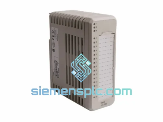
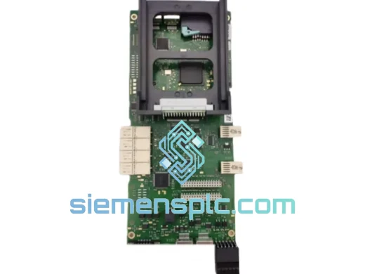
Siemens IMDSI14 Digital Input Module – S800 I/O Series
Request verified availability, condition, replacement risk review, packing options and courier lead time for IMDSI14.
BrandSiemens
Part NumberIMDSI14
ConditionAvailability Check
Lead TimeRFQ Confirmation
DocumentsDatasheet / photos by RFQ
ShippingExport packing available
Auto-filled RFQ
IMDSI14
Click Request Quote and the part number is inserted into the inquiry form automatically.
- Reply by email: [email protected]
- WhatsApp / Tel: +86 18359268345
- Mon-Sat 9:00-18:00 GMT+8
Procurement Data
Key Product Information
Core fields for model confirmation and RFQ routing. Detailed product narrative remains below.
- Brand
- Siemens
- Primary Part Number
- IMDSI14
- Product Type
- Digital Input Module
- Product Family
- Other series
- Manufacturer
- Siemens
- Country of Origin
- DE
- Catalog Category
- I/O Modules
- Operating Temp.
- 0 °C to +60 °C
- Warranty
- 12 months from date of shipment
Model confirmed for inquiry
IMDSI14
Send quantity, destination and urgency. The RFQ form keeps this part number attached.
Request Quote
Product Overview
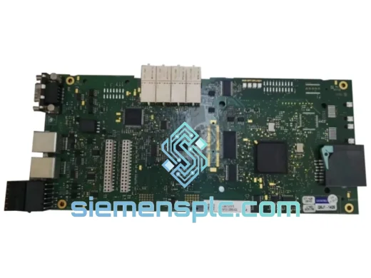
Siemens IMDSI14 48VDC Digital Input Module: Field Signal Acquisition Architecture in High-Integrity DCS Environments
The Siemens IMDSI14 is a 14-channel, 48 VDC digital input module engineered for deployment within high-availability distributed control system architectures. Its primary function is deterministic field signal acquisition — translating discrete electrical states from limit switches, proximity detectors, interlock relays, and push-button stations into structured binary data readable by the process controller over the S800 ModuleBus backplane. In control loops where signal latency or input ambiguity directly affects process safety margins, the IMDSI14 provides the electrical and logical foundation for reliable discrete I/O at the 48 VDC field wiring tier.
The 48 VDC input voltage class is prevalent in legacy process plants, offshore platforms, marine vessel automation, and heavy industrial facilities where 48 V DC bus infrastructure was established as the field wiring standard. The IMDSI14 addresses this segment with a channel architecture that maintains galvanic isolation between each input and the internal ModuleBus, preventing ground loop interference and common-mode noise from propagating into the controller domain. Each of the 14 input channels is independently optocoupled, with the photodiode-transistor pair providing a minimum 500 V isolation barrier between field potential and logic ground. This architecture is not incidental — it is a deliberate EMC design choice that allows the module to operate in environments with high-frequency switching transients from variable-frequency drives, contactors, and solenoid valves operating in close proximity.
Signal conditioning within the IMDSI14 follows IEC 61131-2 Type 1/2 input thresholds. The ON-state voltage window is defined between 30 V and 60 V DC, with the OFF-state threshold below 5 V. The hysteresis band between these thresholds suppresses contact bounce and eliminates nuisance state transitions caused by field wiring capacitance discharge during switch opening. Input filter time constants are configurable via the controller’s I/O configuration tool, allowing engineers to trade off between response speed and noise immunity depending on the application — a 1 ms filter for high-speed interlock detection versus a 10 ms filter for mechanical switch debouncing in less time-critical loops.
The module connects to the S800 I/O station via a passive terminal unit, which provides the physical screw terminal interface for field wiring and the mechanical keying that prevents incorrect module insertion. The ModuleBus interface on the rear of the module carries both power and communication, with the module drawing its operating power from the I/O station’s internal 5 VDC bus — field power at 48 VDC is sourced externally and does not pass through the backplane, maintaining a clean separation between field and system power domains.
Diagnostics are an integral part of the IMDSI14’s value proposition. The module continuously monitors its own internal supply voltage, optocoupler integrity, and communication link status. Any detected fault — whether a blown fuse on the field side, a communication timeout, or an internal hardware error — is reported to the controller as a structured diagnostic message conforming to the S800 I/O diagnostic protocol. This allows the DCS operator station to display channel-level fault information without requiring a field technician to physically inspect the module, reducing mean time to repair in geographically distributed installations.
📩 Real-time Stock & RFQ: [email protected] | WhatsApp: +86 18359268345
Technical Parameters
| Parameter | Specification |
|---|---|
| Manufacturer | Siemens |
| Part Number | IMDSI14 |
| Module Function | Digital Input (DI), 14-channel |
| Rated Input Voltage | 48 VDC |
| ON-State Voltage Range | 30 – 60 VDC |
| OFF-State Voltage Threshold | < 5 VDC |
| Input Current per Channel | Approx. 5 mA at 48 VDC |
| Channel Isolation | Galvanic (optocoupler), ≥ 500 V field-to-bus |
| Signal Standard | IEC 61131-2 Type 1 / Type 2 |
| Input Filter Time | Configurable: 1 ms / 3 ms / 10 ms |
| Backplane Interface | S800 ModuleBus |
| System Power Consumption | ≤ 0.5 W from 5 VDC backplane bus |
| Operating Temperature | 0 °C to +60 °C |
| Storage Temperature | –40 °C to +70 °C |
| Relative Humidity | 5 – 95 %, non-condensing |
| Protection Class | IP20 (module body) |
| Dimensions (W × H × D) | Approx. 30 × 130 × 100 mm |
| Weight | Approx. 100 g |
| Certifications | CE, UL, IEC 61131-2 |
| Compatible Platform | S800 I/O Station (TB820V2, TB840A) |
| Warranty | 12 months from date of shipment |
Hardware Logical Analysis
The IMDSI14’s hardware design reflects a disciplined approach to signal integrity in electrically noisy industrial environments. The following aspects of its physical architecture are worth examining in detail:
Optocoupler Isolation Architecture: Each of the 14 input channels employs a dedicated optocoupler device. The LED side of the coupler is driven by the 48 VDC field signal through a current-limiting resistor network, while the phototransistor output feeds directly into the module’s internal logic ASIC. This one-to-one channel-to-optocoupler mapping eliminates cross-channel coupling that would otherwise occur in multiplexed input designs. The result is that a field-side fault — such as a wiring short or voltage spike — on channel 7 has zero electrical influence on the state of channel 3 or any other channel.
EMC Design and Transient Suppression: The field terminal side of each channel incorporates transient voltage suppression (TVS) diodes rated for IEC 61000-4-5 surge immunity. This protects the optocoupler LED from inductive kickback generated when inductive field devices (solenoids, relay coils) are de-energized. The PCB layout routes field-side traces with maximum separation from logic-side traces, and the ground planes are split at the isolation barrier to prevent capacitive coupling of high-frequency noise across the isolation boundary.
Redundancy Arbitration Logic: In redundant S800 I/O station configurations, two IMDSI14 modules can be installed in mirrored slots. The ModuleBus arbitration logic in the I/O station continuously compares the digital state reported by both modules. If a discrepancy is detected — indicating a hardware fault in one module — the station automatically flags the faulty module and continues operation using the healthy unit without interrupting the control loop. This bumpless switchover is achieved in hardware without requiring controller intervention, keeping the process running during module replacement.
Diagnostic Register Architecture: The module maintains an internal status register that is polled by the controller at each scan cycle. This register encodes channel-level input states, module health flags, and communication watchdog status in a compact binary format. The controller’s I/O driver maps this register directly into the process image, making diagnostic data available to the application program without additional function block overhead. Engineers can implement alarm logic directly in the control program based on module diagnostic bits, enabling automated maintenance alerts without relying on operator observation.
System Integration Benefits
- Deterministic scan-cycle alignment: The IMDSI14 synchronizes its input sampling to the ModuleBus scan cycle, ensuring that all 14 channel states are captured at a consistent point in time. This eliminates temporal skew between channels that would otherwise cause false state transitions in interlock logic comparing multiple inputs.
- Configurable input filtering without hardware changes: Filter time constants are set via software in the DCS engineering tool, allowing maintenance engineers to adjust noise immunity characteristics during commissioning or after field wiring modifications without replacing the module or altering hardware jumpers.
- Channel-level diagnostic transparency: Each channel’s fault status is individually addressable in the controller’s process image. Maintenance systems can poll specific channel diagnostics to generate work orders targeting the exact field device or wiring segment at fault, rather than requiring a technician to inspect the entire I/O station.
- Hot-swap capability: The S800 I/O station supports module replacement under power. The IMDSI14 can be extracted and reinserted while the station remains energized, with the controller automatically re-initializing the module and restoring its configuration from the stored parameter set. Planned maintenance does not require a process shutdown.
- Consistent electrical loading on field devices: The defined input impedance of each channel presents a predictable load to field sensors and switches. This is particularly relevant for two-wire proximity sensors with limited output current capacity, where an undefined or variable input impedance could cause unreliable switching behavior.
- Scalable I/O station architecture: Multiple IMDSI14 modules can be installed in a single S800 I/O station alongside analog input, digital output, and specialty modules. The ModuleBus bandwidth is sufficient to support a fully populated station without introducing scan-cycle jitter, allowing engineers to mix I/O types freely based on process requirements.
- Firmware-independent operation: The IMDSI14’s core input acquisition function operates independently of the controller firmware version. Module parameter sets are stored in the I/O station’s non-volatile memory, ensuring that the module resumes correct operation immediately after a controller restart or firmware update without requiring re-commissioning.
- Compliance with functional safety prerequisites: While the IMDSI14 itself is not a SIL-rated module, its galvanic isolation, diagnostic coverage, and deterministic behavior make it a suitable component in the non-safety layer of a defense-in-depth architecture, where it feeds verified discrete signals into a separate safety instrumented system (SIS) for final safety function execution.
Quality Assurance & Global Logistics
Every Siemens IMDSI14 unit supplied through siemensplc.com is sourced from verified channels with documented provenance. Our procurement process prioritizes factory-sealed, new-in-box stock with intact Siemens serial number labels and manufacturing date codes. For units sourced from certified surplus channels, each module undergoes a structured incoming inspection protocol before being offered for sale:
- Physical inspection: label authenticity, housing integrity, connector pin condition, and absence of rework indicators
- Serial number cross-reference against Siemens product databases where access is available
- Power-on functional test verifying ModuleBus communication and channel state reporting (available on request)
- Anti-static packaging with desiccant and humidity indicator cards, compliant with IEC 61340-5-1 ESD handling requirements
- Full documentation package: product datasheet, declaration of conformity, packing list, and inspection record
Logistics operations are managed from our facility in Xiamen, China, a major export hub with direct access to international freight carriers including DHL Express, FedEx International Priority, and UPS Worldwide Expedited. Standard export documentation — commercial invoice, packing list, certificate of origin — is prepared for every shipment. For customers in regulated industries requiring additional documentation (MSDS, material certificates, or third-party inspection reports), these can be arranged prior to shipment confirmation.
Typical dispatch time for in-stock units is 1–3 business days from purchase order confirmation. International transit times range from 3–7 business days via express courier to major industrial regions in Europe, North America, Southeast Asia, and the Middle East. All shipments are tracked end-to-end, with tracking numbers provided upon dispatch. A 12-month warranty covers manufacturing defects and premature failure under normal operating conditions, with replacement or credit issued following fault verification.
Contact Information
📧 Email: [email protected]
📱 WhatsApp: +86 18359268345
🌐 Web: siemensplc.com
📍 Location: Xiamen, China
© 2026 siemensplc.com. All rights reserved.
Ready to quote
[email protected]
Send This Part Number to Sales
RFQ workflow
Quality workflow ->
Confirmation Process
01Model confirmation
We check the full part number, brand, series and visible nameplate information before quotation.
02Availability reply
Sales confirms stock path, condition option, quantity and realistic lead time for export dispatch.
03Packing & courier
DHL, FedEx, UPS or buyer courier arrangements can be reviewed with packing requirements.
Continue sourcing
Browse full catalog ->
Related Automation Parts
Similar brand or category products for fast comparison and multi-item RFQ lists.
Siemens
RFQ Ready
Siemens 6RY1803-0AA05-0AA1 Digital Output Module
SIMOREG
Origin DE
Digital Output Module