Siemens
In Stock OK
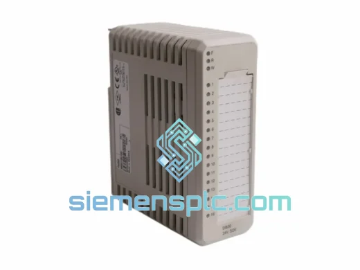
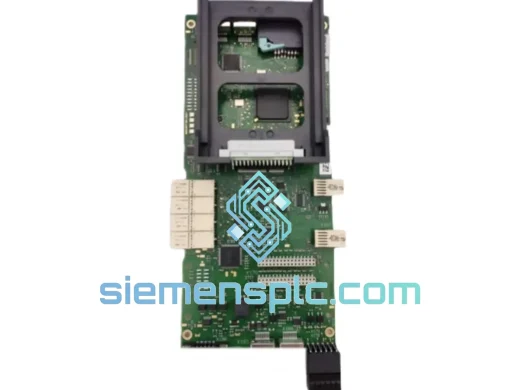
Siemens SPDSI13 Digital Input Module – S+ Series
Request verified availability, condition, replacement risk review, packing options and courier lead time for SPDSI13.
BrandSiemens
Part NumberSPDSI13
ConditionAvailability Check
Lead TimeRFQ Confirmation
DocumentsDatasheet / photos by RFQ
ShippingExport packing available
Auto-filled RFQ
SPDSI13
Click Request Quote and the part number is inserted into the inquiry form automatically.
- Reply by email: [email protected]
- WhatsApp / Tel: +86 18359268345
- Mon-Sat 9:00-18:00 GMT+8
Procurement Data
Key Product Information
Core fields for model confirmation and RFQ routing. Detailed product narrative remains below.
- Brand
- Siemens
- Primary Part Number
- SPDSI13
- Product Type
- Digital Input Module
- Product Family
- Other series
- Manufacturer
- Siemens
- Country of Origin
- DE
- Catalog Category
- I/O Modules
- Operating Temp.
- 0 °C to +60 °C (storage: –40 °C to +85 °C)
- Warranty
- 12 months from date of shipment
Model confirmed for inquiry
SPDSI13
Send quantity, destination and urgency. The RFQ form keeps this part number attached.
Request Quote
Product Overview
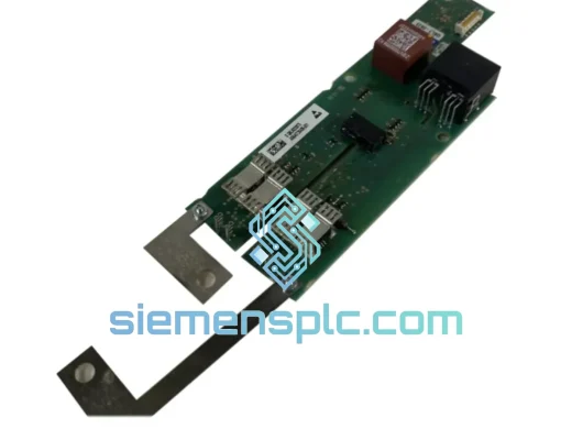
Siemens SPDSI13 Digital Input Module: Discrete Signal Acquisition in High-Integrity DCS Architectures
In distributed control systems where process safety and uptime are non-negotiable, the integrity of discrete signal acquisition at the I/O layer determines the reliability of every upstream control decision. The Siemens SPDSI13 Digital Input Module is a field-hardened component designed to capture binary field device states — valve positions, motor run/stop feedback, limit switch contacts, and interlock signals — and deliver them to the controller backplane with deterministic latency and verified electrical isolation. Its role is not peripheral: in a live DCS loop, a single missed or corrupted digital input can trigger spurious shutdowns, mask equipment faults, or delay safety system responses. The SPDSI13 is engineered to eliminate that failure mode.
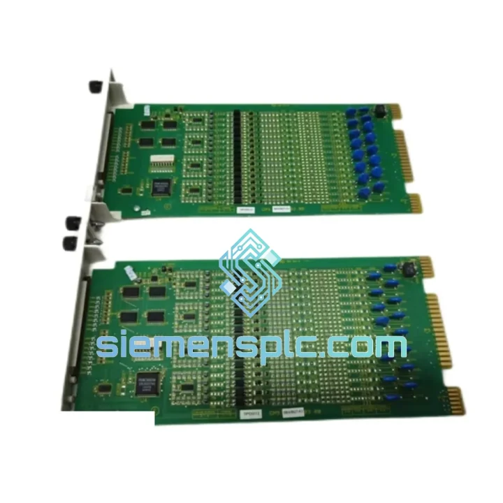
Deployed across power generation, oil and gas, chemical processing, and water treatment facilities, the SPDSI13 integrates into the S+ Series I/O subsystem, communicating with the controller via the high-speed backplane bus. Its channel architecture supports multi-point discrete input scanning with configurable debounce filtering, ensuring that contact bounce from mechanical field devices does not propagate as false state transitions into the control logic. This hardware-level filtering is implemented in dedicated signal conditioning circuitry — not in firmware — which means its behavior is deterministic regardless of controller CPU load.
📩 Real-time Stock & RFQ: [email protected] | WhatsApp: +86 18359268345
Technical Parameters
| Parameter | Specification |
|---|---|
| Part Number | SPDSI13 |
| Manufacturer | Siemens |
| Series | S+ (Symphony Plus) DCS I/O |
| Module Type | Digital Input Module |
| Input Signal Type | Discrete (dry contact / wet contact, configurable) |
| Channel Isolation | Optical isolation per channel group; channel-to-backplane galvanic separation |
| Input Voltage Range | 24 V DC nominal; compatible with standard field loop voltages |
| Signal Debounce | Hardware-implemented RC debounce filtering; configurable time constant |
| Backplane Interface | High-speed S+ controller backplane bus; deterministic scan cycle |
| Diagnostic Coverage | Per-channel open-wire detection; module-level health reporting to S+ Operations |
| Operating Temperature | 0 °C to +60 °C (storage: –40 °C to +85 °C) |
| Relative Humidity | 5% to 95% non-condensing |
| EMC Compliance | IEC 61000-4 series; designed for Class A industrial environments |
| Form Factor | Rack-mount; compatible with S+ I/O chassis and termination assemblies |
| Weight | 360 g |
| Warranty | 12 months from date of shipment |
Hardware Logical Analysis
The SPDSI13’s signal path begins at the field terminal block, where incoming discrete signals pass through transient voltage suppression (TVS) diodes rated for industrial surge environments — a first-stage protection layer that clamps inductive load switching transients before they reach the signal conditioning stage. Each input channel is then routed through an optocoupler isolation barrier. The optocoupler’s LED side is driven by the field signal; the phototransistor side feeds the module’s internal logic domain. This galvanic separation means that ground potential differences between field devices and the control system — a common source of noise injection in large industrial installations — are blocked at the hardware boundary rather than managed in software.
The internal logic domain operates on a regulated, locally derived supply, decoupled from the backplane power rail by a DC-DC converter stage. This architecture prevents backplane-borne noise from coupling into the signal acquisition path. The debounce filter network uses passive RC elements with a time constant selected to reject contact bounce durations typical of industrial-grade relay and limit switch contacts (typically 1–20 ms), while preserving the response speed required for fast interlock signals.
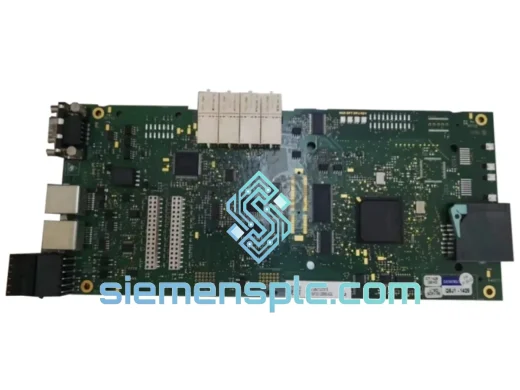
On the backplane interface side, the SPDSI13 implements a register-mapped I/O model. The controller reads channel states from a dual-port memory buffer that is updated by the module’s local scan engine on each acquisition cycle. This decoupling between field scan and controller read ensures that the controller’s backplane access latency does not introduce jitter into the field sampling rate — a critical property in applications where input state timestamps are used for sequence-of-events (SOE) recording.
The module’s EMC design follows IEC 61000-4-2 (ESD), IEC 61000-4-4 (EFT/burst), and IEC 61000-4-5 (surge) test criteria. PCB layout enforces a strict separation between the field-side ground plane and the logic-side ground plane, with the isolation barrier forming the only crossing point. Decoupling capacitors are placed at each power entry point, and signal traces are routed to minimize loop area and reduce susceptibility to radiated interference from adjacent power cabling in marshalling cabinets.
System Integration Benefits
- Deterministic Scan Latency: The local scan engine operates independently of controller CPU load, guaranteeing a fixed acquisition cycle regardless of system-wide processing demand — essential for safety interlock response time budgets.
- Galvanic Channel Isolation: Per-channel optocoupler isolation eliminates ground loop interference paths, reducing nuisance trips caused by common-mode noise in field wiring runs exceeding 100 m.
- Open-Wire Diagnostics: Hardware-level open-circuit detection on each input channel generates a diagnostic flag visible in the S+ Operations HMI without requiring a field inspection, reducing mean time to repair (MTTR).
- Hot-Swap Maintenance: The module supports live insertion and removal within the S+ I/O chassis, allowing replacement during plant operation without requiring a controller restart or process shutdown.
- SOE Timestamp Accuracy: The decoupled scan architecture supports sub-millisecond input state timestamping, meeting the resolution requirements of sequence-of-events recorders used in post-incident analysis.
- Backplane Bus Efficiency: Register-mapped I/O communication minimizes backplane bus occupancy per module, allowing higher I/O density configurations without degrading controller cycle time.
- Unified Diagnostic Transparency: Module health status, channel fault flags, and communication errors are reported through the standard S+ diagnostic framework, visible in the engineering workstation without additional configuration.
- Firmware-Independent Signal Conditioning: Hardware debounce and isolation functions are implemented in discrete circuitry, not firmware, ensuring consistent behavior across controller firmware revisions and eliminating software update risk to signal integrity.
- Wide Operating Temperature Tolerance: Rated for 0–60 °C continuous operation, the module functions reliably in both air-conditioned control rooms and non-climate-controlled marshalling enclosures in tropical or desert environments.
- Direct Drop-In Replacement: Mechanical and electrical compatibility with existing S+ I/O chassis means no wiring modifications, no chassis reconfiguration, and no controller re-engineering on replacement — minimizing planned maintenance window duration.
Quality Assurance & Global Logistics
Every Siemens SPDSI13 unit supplied by siemensplc.com is sourced through traceable procurement channels — authorized distribution networks, decommissioned plant inventories with documented service histories, and certified surplus suppliers. Each unit undergoes a structured pre-shipment inspection protocol: label and marking verification against Siemens manufacturing standards, housing and connector integrity assessment, and where test infrastructure permits, power-on functional verification against a reference S+ backplane.
Shipments originate from Xiamen, China — a major export hub with direct access to DHL Express, FedEx International Priority, UPS Worldwide Express, and consolidated freight forwarding services. Standard export documentation is prepared for every order: commercial invoice, packing list, certificate of origin, and material safety data sheet where applicable. For orders requiring customs pre-clearance documentation or specific country-of-origin certification, our logistics team coordinates the required paperwork prior to dispatch.
Transit times to major industrial regions: Europe (3–5 business days via express courier), Southeast Asia (2–4 business days), Middle East (3–6 business days), North America (4–6 business days). All shipments include real-time tracking and are covered by carrier insurance. ESD-safe packaging with anti-static bags, foam cushioning, and sealed outer cartons is standard for all electronic module shipments. A 12-month warranty against manufacturing defects is included with every unit.
Contact Information
📧 Email: [email protected]
📱 WhatsApp: +86 18359268345
🌐 Web: siemensplc.com
📍 Location: Xiamen, China
© 2026 siemensplc.com. All rights reserved.
Ready to quote
[email protected]
Send This Part Number to Sales
RFQ workflow
Quality workflow ->
Confirmation Process
01Model confirmation
We check the full part number, brand, series and visible nameplate information before quotation.
02Availability reply
Sales confirms stock path, condition option, quantity and realistic lead time for export dispatch.
03Packing & courier
DHL, FedEx, UPS or buyer courier arrangements can be reviewed with packing requirements.
Continue sourcing
Browse full catalog ->
Related Automation Parts
Similar brand or category products for fast comparison and multi-item RFQ lists.
Siemens
RFQ Ready
Siemens 6RY1803-0AA05-0AA1 Digital Output Module
SIMOREG
Origin DE
Digital Output Module