Vibro-Meter
RFQ Ready
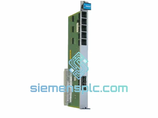
VIBRO-METER VM600 CPU M 200-595-100-032 CPU Module
Origin Switzerland
PLC & DCS CPU Module
Request verified availability, condition, replacement risk review, packing options and courier lead time for VIBRO-METER.
Click Request Quote and the part number is inserted into the inquiry form automatically.
Core fields for model confirmation and RFQ routing. Detailed product narrative remains below.
The VIBRO-METER IPC704P-CP237, catalogued under part number 244-704-000-042, is a single-slot protection card designed for permanent installation within the IPC700 modular rack system. Manufactured by VIBRO-METER SA — a Meggitt Group subsidiary with more than six decades of transducer and machinery protection engineering — this card addresses the specific functional requirement of continuous, channel-resolved vibration monitoring and automatic trip actuation for high-consequence rotating equipment: gas turbines, steam turbines, centrifugal compressors, and large-frame pumps operating in process-critical environments.
The card’s architecture is organized around a strict separation of concerns: signal conditioning, threshold comparison, and relay-drive logic occupy electrically independent functional blocks. This partitioning ensures that a component failure in the analog front-end does not propagate to the trip output, and conversely, that a relay coil fault does not corrupt measurement data reported to the supervisory system. The design approach is consistent with IEC 61511 functional safety requirements applicable to machinery protection in the oil, gas, and power generation sectors.
Each of the four channels operates autonomously. There is no shared comparator bus between channels; a single-channel fault — whether an open-circuit transducer cable or a signal overrange condition — generates a channel-specific fault indication without masking or suppressing the remaining three channels. This independence is a fundamental requirement under API 670 (5th Edition) for critical machinery protection systems.
Real-time Stock & RFQ: [email protected] | WhatsApp: +86 18359268345
| Manufacturer | VIBRO-METER SA (Meggitt Group) |
| Model / SKU | IPC704P-CP237 |
| Part Number | 244-704-000-042 |
| Platform | IPC700 Modular Rack System |
| Card Function | 4-Channel Vibration Protection Unit |
| Supported Transducer Types | IEPE velocity sensors; eddy-current proximity probes (per channel, independently selectable) |
| Measurement Range | Velocity: 0–25 mm/s RMS (configurable); Displacement: 0–500 µm pk-pk (configurable) |
| Frequency Response | 1 Hz – 10 kHz (signal conditioning stage) |
| Galvanic Isolation | 500 V working isolation per channel (optocoupler barrier, analog-to-digital boundary) |
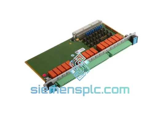
| Trip Relay Output | SPDT dry-contact relay; 250 VAC / 5 A rated; latching on Danger threshold crossing |
| Alert / Danger Setpoints | Independently configurable per channel; stored in non-volatile EEPROM |
| Time Delay to Trip (TDTT) | 0–10 s, independently adjustable per channel |
| Retransmission Output | 4–20 mA per channel (proportional to measured vibration amplitude) |
| Backplane Power Supply | 24 VDC nominal via IPC700 backplane connector |
| Power Consumption | ≤ 8 W per card (all channels active) |
| Operating Temperature | -20 °C to +70 °C |
| Storage Temperature | -40 °C to +85 °C |
| Relative Humidity | 5 % to 95 % RH, non-condensing |
| EMC Compliance | EN 61000-4-2 (ESD), EN 61000-4-4 (EFT, 2 kV), EN 61000-4-5 (Surge, 1 kV), EN 61000-4-6 (Conducted immunity) |
| Slot Footprint | Single-width Eurocard slot, IPC700 backplane |
| Approximate Weight | 1,500 g (module with front panel assembly) |
| Country of Origin | Switzerland |
| Warranty | 12 months from confirmed shipment date |
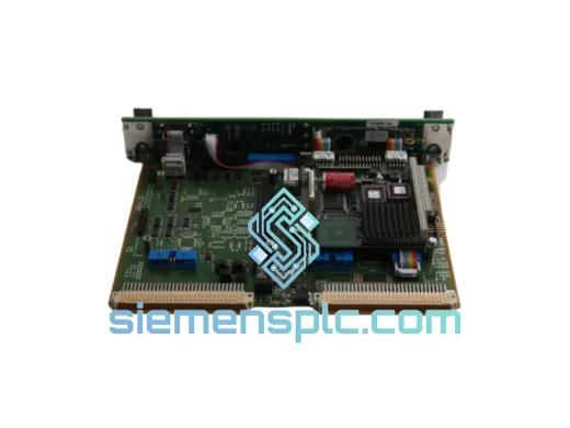
The IPC704P-CP237 implements a protection architecture where the analog signal path and the digital protection logic are physically separated on the PCB by a ground-plane moat. All four analog input channels enter through a passive anti-aliasing filter stage — a second-order Butterworth low-pass with a -3 dB corner at 12 kHz — before reaching the transducer drive circuitry. For IEPE velocity sensors, a constant-current source (typically 4 mA) biases the transducer and the AC-coupled signal is extracted via a blocking capacitor. For eddy-current proximity probes, the card switches to a dedicated oscillator-demodulator circuit that drives the probe cable and recovers the DC gap voltage proportional to shaft displacement.
Galvanic Isolation Architecture: Each channel’s analog measurement signal crosses the isolation barrier via a precision optocoupler rated at 500 V working isolation. This barrier prevents ground-loop currents — endemic in large turbomachinery installations where structural frame potentials can differ by 20–80 V between measurement points — from introducing common-mode noise into the measurement chain. The isolation also protects the backplane logic bus from transient overvoltages induced on long field cable runs during switching events in adjacent motor control centers.
EMC Design Methodology: The PCB employs a split-plane topology: the analog ground plane and the digital logic ground plane are joined at a single star point located at the backplane power entry connector. High-impedance sensor signal traces are routed in a dedicated inner layer, shielded above and below by ground copper pours, and kept physically separated from clock distribution lines by a minimum clearance of 3 mm. The front panel is bonded to chassis ground through a continuous spring-finger contact strip, forming a Faraday enclosure around the analog section. This construction achieves conducted immunity to IEC 61000-4-4 (2 kV EFT burst) and IEC 61000-4-5 (1 kV surge) without requiring external suppression components on field wiring terminals — a significant advantage in installations where terminal block space is constrained.
Threshold Comparison and Relay Latch Logic: Alert and Danger setpoints are stored in non-volatile EEPROM with a write-endurance rating of 1,000,000 cycles, retaining configuration through power interruptions without battery backup. The comparator stage uses hysteresis-controlled window detection with a configurable dead-band of 2–5 % of full scale, preventing relay chatter when measured vibration oscillates near the setpoint. Once a channel crosses the Danger threshold, the trip relay latches and requires an explicit software or hardware reset command — a deliberate design choice that prevents automatic re-energization of machinery following a protective trip without operator acknowledgment.
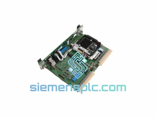
Watchdog-Driven Fail-Safe Relay: The relay coil is driven by a dedicated microcontroller watchdog circuit that monitors the protection processor’s heartbeat signal at 10 ms intervals. If the processor halts, enters an infinite loop, or loses its oscillator reference, the watchdog de-energizes the relay coil within 100 ms, driving the output to the de-energized (trip) state. This fail-safe-to-trip behavior satisfies the architectural requirements for a final element in a SIL 2 machinery protection loop under IEC 61508.
Every IPC704P-CP237 (244-704-000-042) unit supplied through siemensplc.com is procured through verified distribution channels with documented part traceability from manufacturer to end customer. Pre-shipment inspection covers label authenticity, connector pin geometry and plating condition, PCB revision markings against known OEM revision history, and housing dimensional conformance. Where inventory condition permits, functional bench verification is performed against OEM-specified signal parameters prior to dispatch.
A 12-month supply warranty covers defects in materials and workmanship from the confirmed shipment date. Warranty claims are processed within 5 business days of confirmed defect receipt, with replacement unit dispatch or credit note issued accordingly. Certificate of Conformance (CoC) documentation is available upon request for regulated industries including nuclear, aerospace, and offshore oil and gas.
Our logistics operations are based in Xiamen, Fujian Province, China, with direct access to Xiamen Gaoqi International Airport and Xiamen Port — two of China’s primary export hubs for industrial equipment. Standard export documentation prepared for every shipment includes: commercial invoice, packing list, HS code declaration (HS 9030.89 for electronic measuring instruments), and certificate of origin. Typical order processing and dispatch lead time is 1–3 business days from order confirmation.
Email: [email protected]
WhatsApp: +86 18359268345
Web: siemensplc.com
Location: Xiamen, China
© 2026 siemensplc.com. All rights reserved.
We check the full part number, brand, series and visible nameplate information before quotation.
Sales confirms stock path, condition option, quantity and realistic lead time for export dispatch.
DHL, FedEx, UPS or buyer courier arrangements can be reviewed with packing requirements.
Similar brand or category products for fast comparison and multi-item RFQ lists.