Westinghouse
RFQ Ready
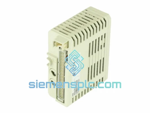
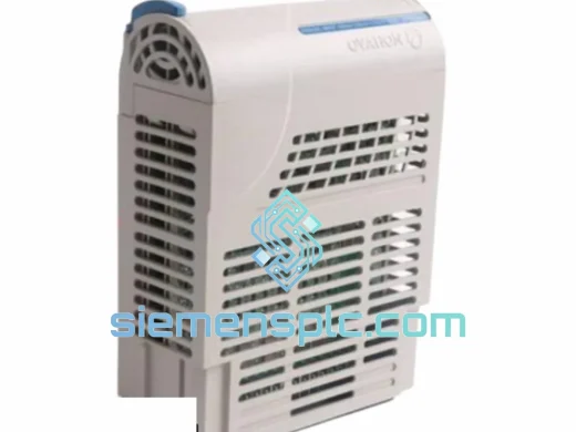
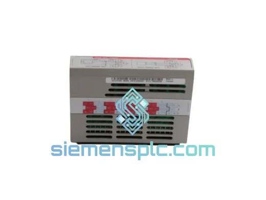
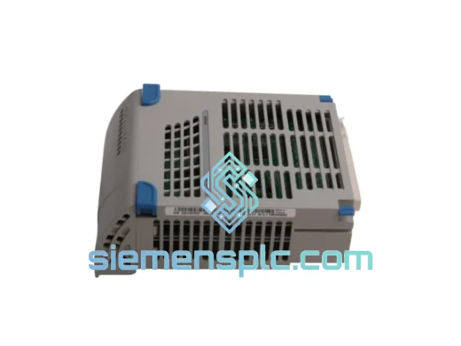
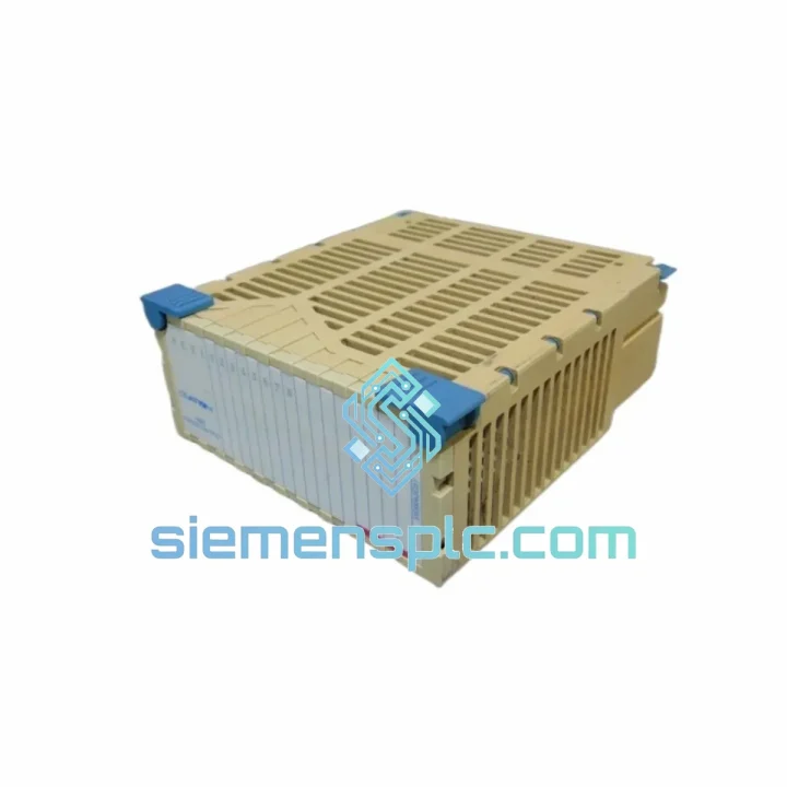
Westinghouse 5X00226G03 I/O Interface Controller
WDPF
Origin US
I/O Interface Controller
Request verified availability, condition, replacement risk review, packing options and courier lead time for 5X00226G02.
Click Request Quote and the part number is inserted into the inquiry form automatically.
Core fields for model confirmation and RFQ routing. Detailed product narrative remains below.
The Westinghouse 5X00226G02 is a rack-mounted analog and discrete I/O signal conditioning card designed for the OCR 400 Distributed Control System platform. Installed at the electrical boundary between field instrumentation and the controller backplane, this module converts raw process signals into isolated, digitized data words consumed by the OCR 400 controller on every deterministic scan cycle. In closed-loop process control, the fidelity of this conversion layer directly governs loop stability, alarm response latency, and the accuracy of engineering-unit values presented at the operator station.
The G02 hardware revision is the second-generation PCB build of the 5X00226 base design. Component-level changes in this revision correct ADC linearity drift identified in early G01 production units under sustained thermal cycling, and introduce improved conducted-EMI filtering on the field wiring terminal block. These modifications extend the module’s reliable service interval in high-ambient-temperature installations — turbine halls, compressor buildings, and fired-heater control rooms where rack cabinet temperatures routinely reach 50 °C under normal operating conditions.
Within the OCR 400 I/O rack, the 5X00226G02 accepts field signals from 4–20 mA two-wire and four-wire transmitters, thermocouple pairs (J, K, and T types), Pt100 RTD elements (3-wire), and dry- or wet-contact discrete inputs. Each analog input channel passes through a dedicated opto-coupler isolation stage, a passive RC anti-aliasing filter, and a 12-bit successive-approximation ADC. The digitized result is stored in an on-board latch register. The OCR 400 controller polls this register during each scan cycle via the rack’s parallel synchronous backplane bus, reading a stable, settled conversion word that is guaranteed coherent regardless of where in the ADC conversion cycle the poll arrives.
The 5X00226G02 is the most widely deployed revision of the 5X00226 card family across power generation, petrochemical refining, pulp-and-paper, and water treatment facilities that standardized on the OCR 400 platform between the mid-1980s and late 1990s. Its continued availability as a verified, inspected spare part is the primary enabler for lifecycle extension programs that maintain OCR 400 platform reliability while deferring full DCS migration capital expenditure. A single failed 5X00226G02 in a critical control loop — with no verified spare on hand — can force an unplanned process shutdown. Stocking a tested replacement eliminates that exposure.
Real-time Stock & RFQ: [email protected] | WhatsApp: +86 18359268345
| Parameter | Specification |
|---|---|
| Part Number | 5X00226G02 |
| Manufacturer | Westinghouse Electric Corporation |
| Target Platform | OCR 400 Distributed Control System |
| Hardware Revision | G02 (second-generation PCB build) |
| Module Function | Analog and discrete I/O signal conditioning interface |
| Form Factor | Single-width rack card, edge-connector backplane mount |
| Backplane Interface | OCR 400 parallel synchronous bus, time-division multiplexed polling |
| Analog Input Types | 4–20 mA current loop; thermocouple J / K / T; RTD Pt100 (3-wire) |
| ADC Architecture | 12-bit successive-approximation register (SAR) |
| ADC Full-Scale Accuracy | ±0.025 % FS at 25 °C after warm-up |
| Current Loop Resolution | ≈ 4 µA per count across 4–20 mA span |
| Field-Side Isolation | Opto-coupler galvanic isolation, ≥ 500 V RMS field-to-logic |
| Anti-Aliasing Filter | Passive RC low-pass, –3 dB ≈ 2 Hz; >40 dB attenuation at 50/60 Hz |
| Discrete I/O | Dry-contact and wet-contact discrete inputs; solid-state discrete output drivers |
| Supply Voltage | 24 VDC nominal, sourced from OCR 400 rack backplane power module |
| Module Power Consumption | ≤ 5 W (excluding field loop excitation current) |
| Operating Temperature | 0 °C to +60 °C (forced-air rack cooling required above 45 °C) |
| Storage Temperature | –20 °C to +70 °C |
| Relative Humidity | 5 % to 95 % RH, non-condensing |
| PCB Substrate | FR-4 glass-epoxy, full acrylic conformal coating per IPC-CC-830 |
| Backplane Connector | DIN-style edge connector, gold-plated contacts |
| Field Wiring Connector | Screw-terminal block, 2.5 mm² conductor capacity |
| Approximate Weight | 340 g |
| Compliance | UL 508 (industrial control equipment); CE marking (at manufacture date) |
| Country of Origin | United States |
| Warranty | 12 months replacement warranty — siemensplc.com |
Per-Channel Opto-Coupler Isolation and Common-Mode Rejection: Each field-side signal input routes through a dedicated opto-coupler stage before reaching the internal analog measurement chain. The isolation barrier establishes a minimum 500 V RMS galvanic separation between the field wiring domain and the backplane logic ground. In large process plants with distributed earthing systems, cable runs exceeding 300 m, and multiple independently grounded equipment enclosures, ground potential differences of 2 V to 8 V between field instruments and control room cabinets are routinely measured. Without galvanic isolation, these potential differences drive common-mode error currents through the 4–20 mA loop burden resistor, introducing a systematic measurement offset indistinguishable from a genuine process variable change and uncorrectable in software. The opto-coupler barrier eliminates this error mechanism at the hardware boundary, preserving ADC accuracy across the full input span regardless of field wiring topology or earthing configuration.
Analog Signal Conditioning Chain and ADC Architecture: The 4–20 mA input path begins with a precision burden resistor network that converts loop current to a differential voltage proportional to the process variable. This differential signal passes through a passive RC low-pass filter with a –3 dB cutoff of approximately 2 Hz, providing greater than 40 dB attenuation at 50 Hz and 60 Hz. This suppresses power-line interference coupled onto field cables sharing cable trays with 480 V and 690 V power conductors — a standard installation condition in process plant marshalling areas. The filtered signal feeds a 12-bit SAR ADC, resolving the 16 mA active span into 4,096 discrete counts at approximately 4 µA per count. This resolution supports 0.025 % full-scale accuracy, meeting the measurement requirements of standard PID control loops for flow, pressure, level, and temperature without requiring software-side linearization corrections for the current input type.
PCB Ground Plane Partitioning and Conducted EMI Suppression: The 5X00226G02 PCB employs a split-plane layout that physically separates the analog signal ground plane from the digital logic ground plane. The analog plane carries the ADC voltage reference, input filter networks, and opto-coupler output stages. The digital plane serves the backplane bus interface logic and data latch registers. The two planes connect at a single star point at the ADC voltage reference pin — the topology that minimizes the impedance path through which digital switching transients couple into the analog measurement domain. Surface-mount ferrite beads are placed in series with all backplane connector signal lines to suppress conducted emissions onto the OCR 400 bus. Decoupling capacitors are positioned at each IC power supply pin with minimized lead lengths to reduce parasitic inductance. The acrylic conformal coating maintains surface insulation resistance above 100 MΩ in high-humidity environments, preventing condensation-induced leakage currents from degrading opto-coupler isolation resistance over the module’s service life.
Backplane Latch-and-Hold Register and Scan-Cycle Determinism: The module participates in the OCR 400 backplane’s time-division multiplexed polling scheme. The controller module acts as bus master and addresses each I/O slot in a fixed, deterministic sequence with a configurable scan period of 100 ms to 500 ms. The 5X00226G02 stores its most recently completed ADC conversion result in a 12-bit data latch register. When the controller issues a read command to the module’s assigned bus slot address, the latch presents the stored conversion word to the backplane data lines within the bus access time defined by the OCR 400 backplane protocol. The controller always reads a stable, settled value — never a word captured mid-conversion. This latch architecture decouples ADC conversion timing from backplane read timing, allowing the module to run its conversion cycle asynchronously while guaranteeing coherent data delivery on every controller scan. The PID execution engine receives a valid, consistent process variable update on every scan cycle, without requiring software-side data validity masking or sample-hold logic in the controller application program.
Every 5X00226G02 unit dispatched from siemensplc.com passes a structured pre-shipment inspection protocol executed at our Xiamen facility. Visual examination covers PCB solder joint integrity across all through-hole and surface-mount components, edge connector pin condition and gold plating continuity, component body status, and conformal coating coverage. Units sourced from decommissioned plant inventories undergo additional screening for thermal stress indicators — discolored PCB substrate, lifted pads, cracked solder joints at high-dissipation components — and for evidence of unauthorized component substitution or field repair work that could compromise long-term reliability in a live control system.
Functional bench verification confirms backplane connector continuity across all signal and power pins, and validates that key active components — the SAR ADC, opto-coupler array, and bus interface logic — respond correctly to controlled stimulus inputs within the specified accuracy limits. Any unit that does not satisfy all inspection criteria is quarantined and excluded from the available inventory pool. Inspection records are retained for each shipped unit.
Packaging follows IEC 61340-5-1 anti-static handling requirements. Each module is placed in a conductive foam tray inside a metallized ESD shielding bag, heat-sealed and labeled with part number and inspection status. The bagged module is packed in a rigid double-wall corrugated carton with molded foam corner inserts rated to withstand the drop and vibration levels specified in ISTA 2A transit testing. This configuration is validated for international air freight and express courier transit on routes to Europe, North America, the Middle East, Southeast Asia, and Australia.
Shipments originate from Xiamen, China — a primary international logistics hub with direct air freight connections to major global distribution centers. Standard delivery timelines via DHL Express or FedEx International Priority are 3–5 business days to Europe and North America, and 2–4 business days to Southeast Asia and the Middle East. Full export documentation — commercial invoice, packing list, certificate of origin, and HS code declaration — is prepared for every international shipment to minimize customs clearance delays at destination ports of entry.
A 12-month replacement warranty covers all units sold through siemensplc.com. Confirmed module failures within the warranty period are addressed with a replacement dispatch within 48 hours of fault verification. Warranty service requires return of the defective unit for technical inspection and root-cause documentation.
Email: [email protected]
WhatsApp: +86 18359268345
Web: siemensplc.com
Location: Xiamen, China
© 2026 siemensplc.com. All rights reserved.
We check the full part number, brand, series and visible nameplate information before quotation.
Sales confirms stock path, condition option, quantity and realistic lead time for export dispatch.
DHL, FedEx, UPS or buyer courier arrangements can be reviewed with packing requirements.
Similar brand or category products for fast comparison and multi-item RFQ lists.