XYCOM
In Stock OK
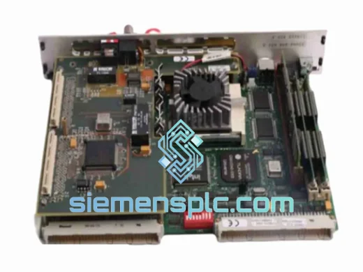
XYCOM XVME-113 VMEbus Relay Output Module – XVME Series
Request verified availability, condition, replacement risk review, packing options and courier lead time for XVME-113.
BrandXYCOM
Part NumberXVME-113
ConditionAvailability Check
Lead TimeRFQ Confirmation
DocumentsDatasheet / photos by RFQ
ShippingExport packing available
Auto-filled RFQ
XVME-113
Click Request Quote and the part number is inserted into the inquiry form automatically.
- Reply by email: [email protected]
- WhatsApp / Tel: +86 18359268345
- Mon-Sat 9:00-18:00 GMT+8
Procurement Data
Key Product Information
Core fields for model confirmation and RFQ routing. Detailed product narrative remains below.
- Brand
- XYCOM
- Primary Part Number
- XVME-113
- Product Type
- VMEbus I/O Module
- Product Family
- Other series
- Manufacturer
- XYCOM Automation (legacy; absorbed into Curtiss-Wright / Kontron lineage)
- Country of Origin
- US
- Catalog Category
- I/O Modules
- Operating Temp.
- 0 °C to +55 °C
- Warranty
- 12 months from date of shipment (siemensplc.com)
- Compliance
- IEEE 1014 VMEbus specification; designed for industrial EMC environments
Model confirmed for inquiry
XVME-113
Send quantity, destination and urgency. The RFQ form keeps this part number attached.
Request Quote
Product Overview
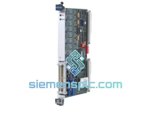
XYCOM XVME-113: VMEbus Relay Output Module for Safety-Critical Industrial Control Loops
The XYCOM XVME-113 is a 6U VMEbus relay output module engineered for deterministic switching in safety-instrumented and process control architectures. Occupying a single VME slot, it interfaces directly with the VMEbus backplane (IEEE 1014) to deliver isolated relay contact outputs under software command from a VME-resident CPU board. Its role in the control loop is unambiguous: it converts digital logic states from the backplane into galvanically isolated dry-contact closures capable of driving field devices — solenoid valves, motor contactors, alarm annunciators, and interlock circuits — without introducing ground loops or common-mode noise into the measurement chain.
In distributed control architectures where the VMEbus chassis serves as the primary I/O concentrator, the XVME-113 occupies the output tier of the signal chain. The CPU board writes to the module’s address-decoded register space via the VME A16/A24 address map; the module’s onboard logic latches the output state and drives the relay coil driver circuit. This architecture ensures that relay state is retained even during brief VME bus arbitration cycles, preventing spurious output transitions during multi-master bus contention.
Real-time Stock & RFQ: [email protected] | WhatsApp: +86 18359268345
Technical Parameters
| Parameter | Specification |
|---|---|
| Manufacturer | XYCOM Automation (legacy; absorbed into Curtiss-Wright / Kontron lineage) |
| Part Number | XVME-113 |
| Module Class | VMEbus Relay Output I/O Module |
| Bus Standard | VMEbus IEEE 1014, 6U form factor |
| Slot Occupancy | Single 6U VME slot |
| Output Type | Dry relay contact (Form C — SPDT) |
| Output Channel Count | 16 relay output channels |
| Contact Rating (Resistive) | 2 A @ 30 VDC / 0.5 A @ 125 VAC |
| Contact Isolation | Galvanic isolation between VME logic and field contacts |
| Backplane Supply Voltage | +5 VDC (VME P1 connector, standard backplane rail) |
| Logic Power Consumption | ≤ 3.5 W typical from +5 VDC rail |
| Address Space | VME A16 short I/O / A24 standard (jumper-selectable base address) |
| Data Transfer Width | D8 / D16 (byte and word access) |
| Operating Temperature | 0 °C to +55 °C |
| Storage Temperature | −40 °C to +85 °C |
| Relative Humidity | 5% to 95% non-condensing |
| Module Dimensions | 233.35 mm × 160 mm (6U × 1 slot) |
| Weight | Approx. 610 g |
| Connector | VME P1 (96-pin DIN 41612) + P2 I/O connector for field wiring |
| Compliance | IEEE 1014 VMEbus specification; designed for industrial EMC environments |
| Warranty | 12 months from date of shipment (siemensplc.com) |
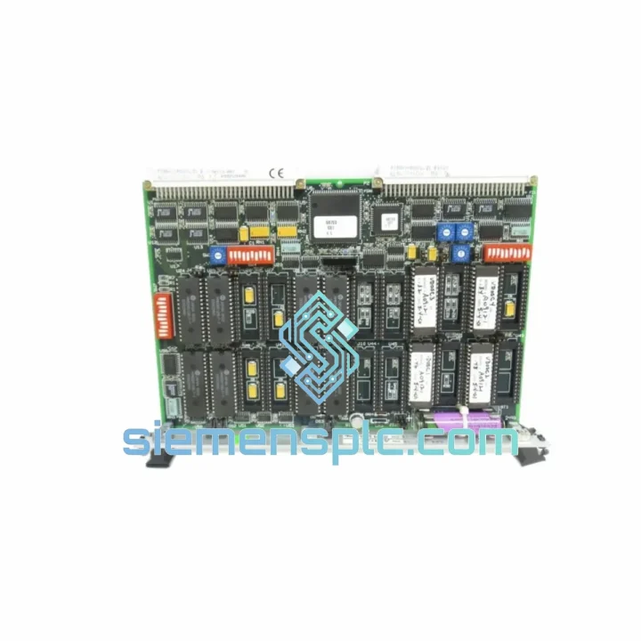
Hardware Logical Analysis
The XVME-113’s hardware architecture reflects the design philosophy of late-generation XYCOM VME I/O boards: deterministic output latching, field-side galvanic isolation, and address-space flexibility via onboard jumper configuration.
Address Decoding and Register Latch Architecture: The module implements a PAL-based (Programmable Array Logic) address decoder that monitors the VME address bus during WRITE cycles. When the CPU asserts a valid address within the module’s configured base address window, the decoder enables the data bus transceivers and clocks the output data into a set of D-type flip-flop latches — one per relay channel. The latched state drives the relay coil driver transistors. This latch-on-write architecture means relay states are non-volatile with respect to bus activity: a relay energized by a WRITE cycle remains energized regardless of subsequent bus transactions until explicitly de-energized by another WRITE. This is a critical safety property — it prevents relay chatter during VME bus resets or CPU reboots unless the application software explicitly clears the output register.
Relay Coil Driver and Flyback Suppression: Each relay coil is driven by a discrete NPN transistor switch. A transient suppression diode (flyback diode) is placed across each relay coil to clamp the inductive kickback voltage generated when the coil is de-energized. Without this suppression, the collapsing magnetic field would generate voltage spikes of 50–200 V on the +5 VDC logic rail, potentially corrupting adjacent VME board logic. The XVME-113’s per-channel flyback suppression ensures that relay switching events do not propagate noise onto the shared VME backplane power rails.
Galvanic Isolation Boundary: The isolation boundary between the VME logic domain (+5 VDC referenced to VME GND) and the field contact domain is implemented via the relay coil-to-contact mechanical separation. The relay contacts are fully floating — no common reference exists between the VME logic ground and the field circuit. This allows the XVME-113 to switch field circuits operating at different voltage potentials (up to 125 VAC or 30 VDC) without creating ground loops that would corrupt analog measurement signals in co-located analog input modules.
EMC Design Considerations: The PCB layout routes high-frequency VME bus signals (data, address, control lines operating at VME’s 16 MHz maximum clock) away from the relay coil driver traces. The relay coil driver section is treated as a separate switching power domain with localized decoupling capacitors on the +5 VDC supply pins. This partitioning reduces the probability of relay switching transients coupling into the VME bus signal traces via PCB parasitic capacitance.
Jumper-Configurable Base Address: The module’s VME base address is set via a bank of DIP switches or jumpers on the PCB, allowing multiple XVME-113 modules to coexist in the same VME chassis without address conflicts. The address map supports both A16 (short I/O, 64 KB space) and A24 (standard, 16 MB space) modes, providing compatibility with both legacy XYCOM CPU boards and third-party VME controllers.
System Integration Benefits
- 1. Non-Volatile Output State Retention: Relay states are held in hardware latches independent of VME bus activity. A CPU watchdog reset or bus timeout does not cause relay outputs to toggle, preserving the last commanded state until software explicitly changes it — a fundamental requirement in process safety applications where undefined output transitions are unacceptable.
- 2. Zero Ground Loop Risk on Field Circuits: Fully floating relay contacts eliminate the common-mode coupling path between the VME logic ground and field device circuits. Analog input modules sharing the same chassis are not affected by relay switching events, maintaining measurement accuracy in mixed analog/digital I/O configurations.
- 3. Direct VME Backplane Integration — No Gateway Required: The XVME-113 maps directly into the VME address space. The CPU reads and writes relay states via standard VME WRITE cycles with no intermediate protocol conversion, serial communication overhead, or fieldbus latency. Output update latency is bounded by VME bus arbitration time, typically sub-microsecond in single-master configurations.
- 4. Deterministic Output Update Timing: In a VME system with a real-time OS (VxWorks, LynxOS, QNX), the relay output update cycle is deterministic and schedulable. The application task can update all 16 relay outputs in a single D16 WRITE cycle, ensuring synchronous output transitions across all channels — critical for coordinated interlock sequences.
- 5. Compatibility with Legacy XYCOM VME Ecosystems: The XVME-113 is register-compatible with existing XYCOM driver libraries and BSPs (Board Support Packages). Integrating this module into an existing XYCOM-based system requires no driver development — the existing I/O abstraction layer handles the module transparently, reducing integration engineering effort to near zero.
- 6. Reduced Panel Wiring Complexity: Sixteen relay outputs on a single 6U VME card replace sixteen discrete relay modules that would otherwise require individual DIN-rail mounting, individual power wiring, and individual coil suppression components. This consolidation reduces panel wiring density, lowers the probability of wiring errors, and simplifies panel inspection and maintenance.
- 7. Diagnostic Readback Capability: The module supports output register readback — the CPU can read the current state of the output latch register and compare it against the commanded state. This allows the application software to implement output verification loops, detecting relay driver failures (open-circuit coil, failed transistor) without requiring external feedback wiring.
- 8. Scalable I/O Expansion within VME Chassis: Additional XVME-113 modules can be added to vacant VME slots to expand relay output capacity in 16-channel increments. A standard 21-slot VME chassis can accommodate up to 20 XVME-113 modules (reserving one slot for the CPU), providing up to 320 relay output channels within a single chassis — a density that would require multiple separate relay panels in a discrete relay architecture.
Quality Assurance & Global Logistics
Every XYCOM XVME-113 unit supplied by siemensplc.com undergoes a documented pre-shipment inspection protocol. Each module is powered up in a VME test chassis, the output register is written with alternating bit patterns (0x5555 / 0xAAAA), and relay actuation is verified on all 16 channels using a continuity test fixture. Modules that fail any channel are quarantined and not shipped. Only units that pass full 16-channel functional verification are released for sale.
Units are shipped in anti-static shielding bags, placed in foam-lined rigid cartons, and sealed with tamper-evident tape. Each shipment includes a packing list with the module serial number, test date, and technician ID for full traceability. A 12-month warranty against functional defects is provided from the date of shipment.
Logistics operations are based in Xiamen, China. Standard export routes include:
- DHL Express / FedEx International Priority: 3–5 business days to Europe, North America, Southeast Asia
- UPS Worldwide Expedited: 4–7 business days, cost-optimized for mid-weight shipments
- Air Freight (forwarder): For multi-unit orders where express courier dimensional weight pricing is prohibitive
- Sea Freight (LCL/FCL): Available for bulk orders; transit 15–30 days depending on destination port
Export documentation — commercial invoice, packing list, Certificate of Origin, and HS code 8537.10 classification — is prepared as standard for all international shipments. Customs pre-clearance support is available for regulated-industry buyers in the EU, US, and Australia.
Contact Information
Email: [email protected]
WhatsApp: +86 18359268345
Web: siemensplc.com
Location: Xiamen, China
© 2026 siemensplc.com. All rights reserved.
Ready to quote
[email protected]
Send This Part Number to Sales
RFQ workflow
Quality workflow ->
Confirmation Process
01Model confirmation
We check the full part number, brand, series and visible nameplate information before quotation.
02Availability reply
Sales confirms stock path, condition option, quantity and realistic lead time for export dispatch.
03Packing & courier
DHL, FedEx, UPS or buyer courier arrangements can be reviewed with packing requirements.
Continue sourcing
Browse full catalog ->
Related Automation Parts
Similar brand or category products for fast comparison and multi-item RFQ lists.
XYCOM
RFQ Ready
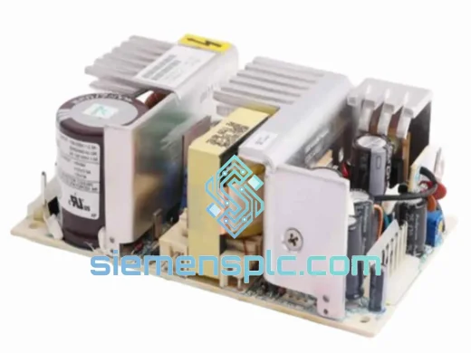
XYCOM XVME-976 VMEbus Power Supply – XVME Series
XVME Series
Origin US
VMEbus Power Supply
XYCOM
RFQ Ready
XYCOM XVME-500 VMEbus Power Supply Module
Ready to Ship
Origin US
VMEbus Power Supply