Yokogawa
RFQ Ready
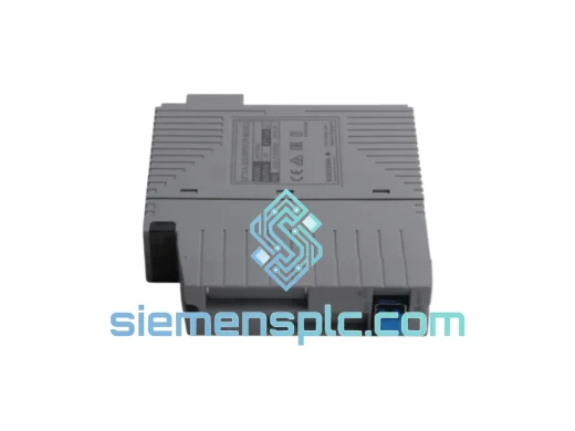
YOKOGAWA EB401-10 DCS Interface Module – CENTUM VP / CS 3000
CENTUM VP
Origin JP
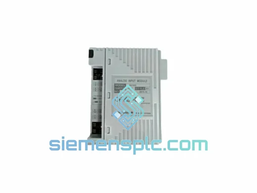
DCS Interface Module
Request verified availability, condition, replacement risk review, packing options and courier lead time for NFDV561-P00.
Click Request Quote and the part number is inserted into the inquiry form automatically.
Core fields for model confirmation and RFQ routing. Detailed product narrative remains below.
The YOKOGAWA NFDV561-P00 S2 occupies the terminal execution layer of the CENTUM VP distributed control architecture. Mounted within the Field Control Station (FCS) I/O node rack, this 16-channel relay-contact digital output module receives discrete command frames from the FCS CPU via the Vnet/IP backplane bus and translates them into dry-contact relay closures. Field loads driven by these contacts include solenoid valve coils, motor starter contactor coils, alarm horn circuits, and hardwired interlock relay panels. Because the module operates under the FCS deterministic scan engine, output actuation timing is bounded to one scan period plus relay operate time — a measurable, documentable latency figure that process engineers can formally cite in loop performance records and SIL verification worksheets for non-safety-rated interlock functions.
The S2 hardware revision designation marks the second production generation of the NFDV561-P00 platform. Compared to the original release, the S2 incorporates revised relay contact alloy metallurgy, updated optocoupler circuitry with improved common-mode rejection ratio (CMRR), and a refined four-layer PCB layout that reduces inter-channel crosstalk at elevated switching frequencies. The S2 is mechanically and electrically interchangeable with first-generation NFDV561-P00 units across all standard CENTUM VP I/O node rack configurations, qualifying it as a verified drop-in replacement for brownfield DCS maintenance, capacity expansion, and critical spare standardization programs — without requiring control application re-download or I/O builder tag reconfiguration.
Real-time Stock & RFQ: [email protected] | WhatsApp: +86 18359268345
| Parameter | Specification |
|---|---|
| Part Number / SKU | NFDV561-P00 S2 |
| Manufacturer | YOKOGAWA Electric Corporation |
| Module Function | Digital Output (DO) — Relay Contact, Normally Open (NO) |
| Compatible Platform | CENTUM VP / CS 3000 FCS I/O Subsystem |
| Output Channel Count | 16 channels, electrically independent relay contacts |
| Contact Rating — Resistive Load | 250 VAC / 30 VDC, 2 A per channel |
| Contact Rating — Inductive Load | 250 VAC / 30 VDC, 0.5 A per channel (L/R ≤ 7 ms) |
| Relay Operate Time | ≤ 10 ms (coil energized → contact closed) |
| Relay Release Time | ≤ 5 ms (coil de-energized → contact open) |
| Contact Bounce Duration | < 2 ms (S2 revision) |
| Mechanical Cycle Life | ≥ 10,000,000 operations (no load) |
| Electrical Cycle Life | ≥ 100,000 operations at rated resistive load |
| Field-Side Isolation Voltage | 500 V RMS (field wiring to backplane bus) |
| Channel-to-Channel Isolation | Independent relay contact per channel; no shared common rail |
| Common-Mode Noise Rejection | > 1 kV peak (optocoupler stage) |
| Backplane Communication Bus | Vnet/IP (100 Mbps deterministic Ethernet-based fieldbus) |
| FCS Scan Cycle Compatibility | 100 ms / 200 ms / 500 ms / 1 s (configurable in I/O builder) |
| Operating Temperature | 0 °C to +55 °C |
| Storage Temperature | −25 °C to +70 °C |
| Relative Humidity | 5 % to 95 % RH, non-condensing |
| PCB Stackup | 4-layer with dedicated ground planes |
| Module Weight | Approx. 210 g |
| Form Factor | Single-slot CENTUM VP standard I/O module |
| Certifications | CE, UL Listed, IECEx (variant-dependent) |
| Warranty | 12 months from confirmed shipment date |
Per-Channel Optocoupler Isolation Architecture: Each of the 16 output channels integrates a dedicated optocoupler between the Vnet/IP-connected backplane logic bus and the relay coil driver transistor. This galvanic barrier sustains 500 V RMS isolation, blocking field-side transient voltages from propagating to the FCS backplane. In process plant environments where variable-frequency drives (VFDs) and thyristor-controlled rectifiers generate broadband conducted emissions on shared cable trays, the optocoupler stage provides common-mode noise rejection exceeding 1 kV peak — a margin that prevents false relay actuation events caused by capacitive coupling from adjacent high-voltage motor feeder cables.
Bifurcated AgCdO Relay Contact Metallurgy: The S2 revision specifies bifurcated silver-cadmium oxide (AgCdO) relay contacts. The bifurcated geometry maintains two parallel conduction paths per channel. If one contact surface develops a localized oxide film — a degradation mode common in low-current dry-circuit applications where insufficient arc energy prevents self-cleaning — the parallel path sustains electrical continuity. Contact bounce duration is held below 2 ms in the S2 hardware, which is operationally significant for downstream edge-triggered logic or pulse-counter function blocks within the FCS application; bounce durations exceeding 5 ms can generate spurious count increments in counter blocks monitoring relay state transitions.
Four-Layer PCB Ground Plane EMC Strategy: The module PCB uses a four-layer stackup in which signal routing layers are sandwiched between dedicated copper ground planes acting as distributed Faraday shields. Relay coil driver lines carry ferrite bead filters at the PCB entry point to suppress back-EMF transients generated during relay de-energization — transients that, without suppression, can reach 50–100 V peak on the driver line and couple into adjacent signal traces via parasitic capacitance. The module housing uses conductive-coated polymer, providing supplementary shielding effectiveness of approximately 20 dB across the 30 MHz–1 GHz band, consistent with EN 61000-4-3 Class A industrial radiated immunity requirements.
EEPROM-Backed Hold-Last-State Latch Register: In dual-redundant CENTUM VP FCS configurations, the NFDV561-P00 S2 implements a local EEPROM-backed output latch register. During a primary-to-standby controller switchover — a transition window typically under 100 ms — the module holds its last commanded output state autonomously, without requiring a refresh command from the incoming active controller. This behavior prevents spurious relay de-energization during switchover, which would otherwise cause unintended valve closures or motor trips in continuous-process applications. The latch state is preserved even if the Vnet/IP bus loses frame synchronization during the switchover interval, ensuring field actuator state continuity through the entire bumpless transfer sequence.
Every YOKOGAWA NFDV561-P00 S2 unit dispatched from siemensplc.com undergoes a structured pre-shipment inspection before release. Physical authentication confirms label integrity, S2 hardware revision markings, connector pin geometry, and housing condition against reference samples. Functional verification applies 24 VDC field-side power and exercises all 16 relay channels through a complete operate-release cycle, measuring contact resistance (acceptance criterion: <100 mΩ per channel at 100 mA test current) and operate time against the published YOKOGAWA specification. Units that fail any criterion are quarantined and excluded from available stock.
All shipments originate from our Xiamen, China warehouse. Standard dispatch lead time is 2–3 business days from payment confirmation. International freight is routed via DHL Express, FedEx International Priority, and UPS Worldwide Expedited, with typical transit times of 3–5 business days to European, Middle Eastern, and Southeast Asian destinations. Each shipment includes a commercial invoice, packing list, and certificate of origin to support import customs clearance. EXW Xiamen and FOB Xiamen Incoterms are both available. Orders of 5 units or more qualify for consolidated freight rate negotiation. A 12-month warranty covers all supplied units against manufacturing defects and functional failure under normal operating conditions as defined in the YOKOGAWA product specification. Warranty claims are acknowledged within 2 business days and replacement units dispatched from available stock where inventory permits.
Email: [email protected]
WhatsApp: +86 18359268345
Web: siemensplc.com
Location: Xiamen, China
© 2026 siemensplc.com. All rights reserved.
We check the full part number, brand, series and visible nameplate information before quotation.
Sales confirms stock path, condition option, quantity and realistic lead time for export dispatch.
DHL, FedEx, UPS or buyer courier arrangements can be reviewed with packing requirements.
Similar brand or category products for fast comparison and multi-item RFQ lists.