
A digital input that stays on after a sensor changes state is not automatically a failed PLC module. The electrical off state must satisfy the input’s requirements. With a two-wire sensor, residual current is one part of that assessment, and an incorrect assumption can lead to a replacement card that behaves exactly like the removed one.
For an SM 321 spare request, preserve the complete module and sensor identities before assigning the fault. This evergreen guide explains how to organize the evidence around a 6ES7321-1BL00-0AA0 installation. It does not prescribe a field wiring modification or a resistor value.
Off does not always mean zero current
Siemens’ data sheet for 6ES7321-1BL00-0AA0 specifies a maximum permissible two-wire sensor quiescent current of 1.5 mA. It gives an input-voltage range of -30 to +5 V for signal zero and 13 to 30 V for signal one. The nominal 24 V designation does not replace these separate input-state requirements.
Those figures describe this exact module. They are not a general allowance for every SM 321 variant or every device sold as a 24 V sensor. The sensor’s specified behavior and the actual circuit arrangement must be assessed against the matching input documentation.
A sensor’s visual indication, an HMI symbol and a PLC input state are different observations. Record each one separately. If they disagree, the discrepancy is useful diagnostic evidence; it should not be concealed by assuming they all represent the same electrical condition.
Preserve the full order number
The 6ES7321-1BL00-0AA0 SM 321 input module is a specific sourcing reference. Use it only when it matches the installed and approved requirement. Record the front connector, channel assignment and relevant drawing revision as part of the spare work pack.
A 6ES7321-1BH02-0AA0 input module is a different order code, not an automatic substitute selected by the SM 321 family name. Its suitability must be assessed using its own documentation and the application requirements. A procurement comparison should make the difference visible rather than shorten both references to digital input card.
The same discipline applies to the sensor. Record the complete reference, wiring arrangement and output characteristics. A change of sensor brand or suffix may matter even when the bracket, sensing distance and supply label look unchanged.
Collect a circuit-specific fault record
A useful record names the affected machine state, sensor state, PLC channel and application observation. Note whether the symptom appeared after a sensor change, cable repair, module replacement or program modification. Preserve the chronology without declaring a cause before it has been evaluated.
Capture the approved circuit drawing and identify any intervening device, connector or indicator. The input may not be connected to the sensor in the simple way assumed from a cabinet label. A drawing discrepancy should be resolved by the responsible team, not patched over with an undocumented spare substitution.
Measurements, where necessary, require qualified personnel and a safe approved method. Record the reference point, instrument, circuit state and result. A voltage observed with a different loading condition may not answer the question of how the installed input responds. Keep that context with the number so another engineer can interpret it later.
Avoid an unreviewed field modification
It can be tempting to add a component to force the input off or to alter application logic until the display looks correct. Either action can hide the original mismatch and create a new maintenance dependency. Do not implement a generic internet remedy without evaluating the actual circuit, component ratings and machine behavior.
Instead, establish whether the sensor and input requirements are compatible, whether the installed wiring matches the approved design, and whether the observed logic is interpreted correctly. If a design change is needed, document it through the plant’s engineering process. The replacement order should then reflect the approved design rather than an improvised workaround.
This approach is particularly important when the input participates in a permissive or sequence transition. A seemingly small change in off-state behavior can affect what the application believes about the machine. Operational acceptance belongs to the responsible control-system team, not to the person processing the purchase order.
Use the spare to answer a defined question
A bench check of a candidate module should have a stated scope. It can establish identity and behavior under documented test conditions, but it cannot prove every field sensor and cable on the production line. Keep receiving inspection, fault investigation and final machine acceptance as separate records.
If a replacement is installed under an approved plan, record whether the original symptom remains and which other conditions changed. Replacing the card and sensor together may restore operation, but it does not by itself identify which item caused the fault. An accurate maintenance history helps future stock decisions more than an unsupported conclusion.
Send SiemensPLC the full installed order number, sensor reference, label photographs and required delivery scope. Request identification and test evidence for the offered spare. Keep any proposed circuit or application change subject to the plant’s own engineering approval.
Frequently Asked Questions
Does a sensor indicator going out prove that the PLC input is off?
No. The indicator and the electrical input state are separate observations. Check the exact sensor and input requirements, circuit arrangement and approved diagnostic evidence. Do not infer the PLC’s accepted state solely from a lamp on the sensor housing.
Is the 1.5 mA limit universal for SM 321 modules?
No. The cited value applies to the specified 6ES7321-1BL00-0AA0 data sheet. Other order codes need their own documentation. Preserve the complete reference when comparing sensors, modules and proposed spare substitutions.
Should we add a resistor to make an input switch off?
Not as an unreviewed remedy. Any circuit change requires application-specific assessment and approval, including component ratings and machine behavior. First establish the compatibility and fault evidence. This article does not provide a universal modification instruction.
Will a new module fix every stuck-on symptom?
No. Sensor characteristics, wiring, intervening devices and application interpretation may contribute. A new module can reproduce the same behavior if the underlying circuit mismatch remains. Use a documented investigation and acceptance plan rather than repeated speculative replacements.
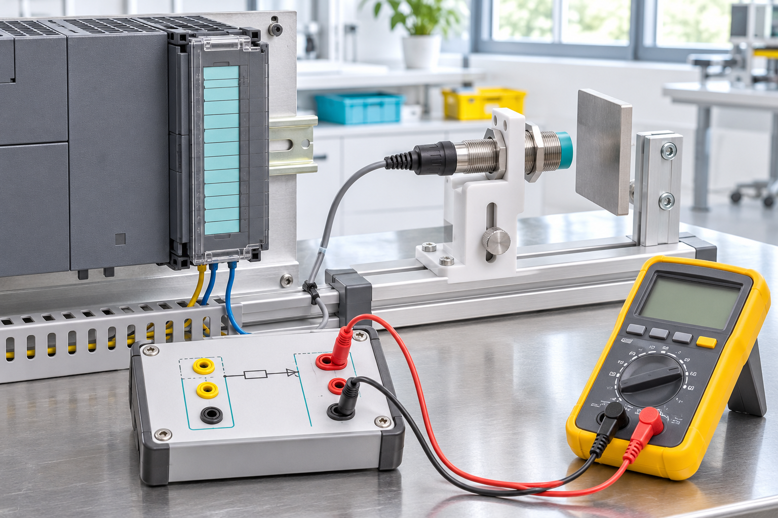
Image: AI-generated editorial illustration, not an exact product photograph or installation reference.
© 2026 SiemensPLC. All rights reserved. Official Website: https://siemensplc.com Inquiry: [email protected] | WhatsApp/Tel: +86 18359268345