Allen-Bradley
RFQ Ready
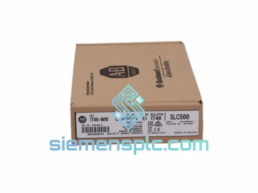
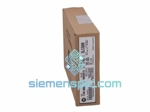
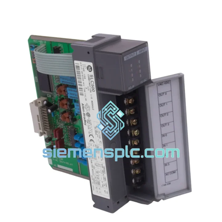
Allen-Bradley DIM16 Discrete Input Module
SLC 500
Origin US
Discrete Input Module
Request verified availability, condition, replacement risk review, packing options and courier lead time for 1746-IO8.
Click Request Quote and the part number is inserted into the inquiry form automatically.
Core fields for model confirmation and RFQ routing. Detailed product narrative remains below.
In discrete manufacturing environments where rack space is a finite resource and I/O balance is a design constraint, the Allen-Bradley 1746-IO8 addresses both simultaneously. This single-slot combination module integrates four 24 VDC discrete inputs and four transistor outputs into one 1746-series card, eliminating the need to allocate two separate slots for equivalent I/O capacity. The result is a measurable reduction in rack footprint, backplane current draw, and wiring termination points — without any compromise to signal integrity or switching performance.
The 1746-IO8 operates within the SLC 500 control platform, a distributed programmable controller architecture that Rockwell Automation introduced for mid-range discrete and process applications. The module communicates over the 1746 backplane using the SLC 500 I/O scan protocol, where the processor reads input image data and writes output image data on every program scan cycle. Scan cycle determinism is governed by the SLC 500 processor’s RPI (Requested Packet Interval) configuration, not by the I/O module itself, which means the 1746-IO8 responds to output commands within one backplane scan after the processor updates the output image table.
The optical isolation barrier between the field-side terminal block and the backplane logic circuitry is rated at 1500 VAC continuous. This isolation is implemented using phototransistor couplers on each input channel, which convert field-side current flow into an optical signal that crosses the isolation boundary without any galvanic connection. On the output side, the transistor switching elements are similarly isolated, protecting the backplane from inductive kickback generated by solenoid valve coils, relay coils, and motor brake circuits. This architecture conforms to IEC 61131-2 isolation requirements for programmable controller I/O modules.
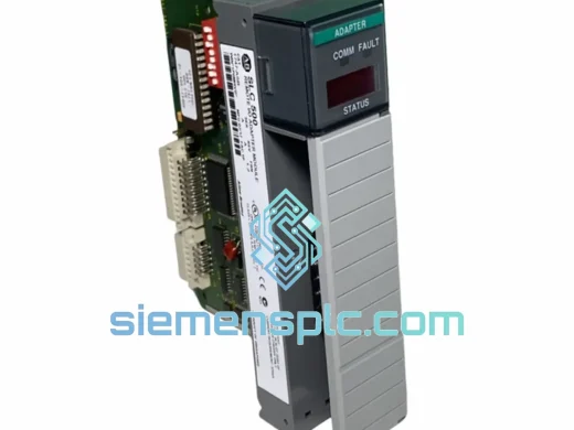
The removable terminal block (RTB) design is a practical maintenance feature with measurable impact on mean time to repair. Field wiring terminates on the RTB, which latches onto the module face. During a module replacement, the RTB is unlatched and transferred to the replacement module without disturbing any field wiring. In a production environment where rewiring a 20-point terminal block can take 45–90 minutes, the RTB mechanism reduces module swap time to under five minutes, directly compressing unplanned downtime duration.
Input channel filtering is implemented in hardware using RC networks on each input line, providing noise immunity against transient spikes below the filter time constant. The default input filter time is 1 ms, which rejects electrical noise from adjacent motor drives, contactors, and switching power supplies while remaining fast enough to capture sensor signals from standard proximity switches and photoelectric sensors operating at frequencies up to 500 Hz. The filter time is fixed in hardware and is not software-configurable on this module series.
Output channel protection includes internal current limiting and thermal shutdown circuitry. Each output transistor is rated at 1 A continuous with a 2 A surge capability for inrush-limited loads such as incandescent pilot lights and solenoid valve coils at energization. The module-level output current limit is 4 A total across all four output channels, which must be observed when all outputs are simultaneously energized at maximum load. Exceeding this aggregate limit activates the thermal protection circuit, which de-energizes all outputs and sets a fault bit in the SLC 500 I/O status file, providing diagnostic transparency at the processor level.
The 1746-IO8 draws 100 mA from the 5 VDC backplane supply and 0 mA from the 24 VDC backplane supply. Field-side power for both inputs and outputs is sourced externally from the user’s 24 VDC field power supply, which must be sized to cover the aggregate input current consumption and output load current. This separation of backplane logic power and field power is a fundamental SLC 500 architecture principle that prevents field-side faults from affecting processor operation.
📩 Real-time Stock & RFQ: [email protected] | WhatsApp: +86 18359268345
| Parameter | Specification |
|---|---|
| Part Number | 1746-IO8 |
| Platform | SLC 500 / 1746 Series |
| Module Type | Combination Discrete I/O |
| Input Channels | 4 × DC discrete inputs |
| Output Channels | 4 × DC transistor outputs |
| Input Voltage Range | 10–30 VDC (nominal 24 VDC) |
| Input ON-State Current | ≥ 6 mA at 24 VDC |
| Input OFF-State Voltage | ≤ 5 VDC |
| Input Filter Time | 1 ms (hardware fixed, RC network) |
| Output Voltage Range | 10–30 VDC |
| Output Current per Point | 1 A continuous; 2 A surge |
| Output Current per Module | 4 A aggregate maximum |
| Output Leakage Current (OFF) | ≤ 1 mA at 30 VDC |
| Output Voltage Drop (ON) | ≤ 1 VDC at rated current |
| Isolation Voltage | 1500 VAC (field to backplane) |
| Backplane Current (5 VDC) | 100 mA |
| Backplane Current (24 VDC) | 0 mA |
| Rack Slots Required | 1 slot (1746 modular rack) |
| Terminal Block | Removable 20-pin RTB |
| Operating Temperature | 0 °C to +60 °C |
| Storage Temperature | −40 °C to +85 °C |
| Relative Humidity | 5–95% non-condensing |
| Vibration Resistance | 2 g @ 10–500 Hz (IEC 68-2-6) |
| Shock Resistance | 30 g operational (IEC 68-2-27) |
| Certifications | UL Listed, CE Marked, CSA Certified |
| Standards Compliance | IEC 61131-2, RoHS |
| Weight | ~400 g (with RTB) |
| Country of Origin | United States |
| Warranty | 12 months from shipment date |
Optical Isolation Architecture: Each of the four input channels employs a dedicated phototransistor coupler. When field-side current exceeds the ON-state threshold (≥ 6 mA), the LED within the coupler activates, forward-biasing the phototransistor on the logic side. This generates a logic-level signal that the backplane interface ASIC reads and maps into the SLC 500 input image table. The galvanic break at the coupler boundary means that field-side ground potential differences of up to 1500 VAC cannot propagate into the backplane logic domain — a critical protection mechanism in facilities where field devices share ground references with variable-frequency drives or welding equipment.
Output Transistor Topology: The output stage uses NPN or PNP transistor configurations (depending on module variant) with integrated flyback diode protection across each switching element. When an inductive load such as a solenoid valve coil is de-energized, the collapsing magnetic field generates a reverse EMF spike. The flyback diode clamps this spike to the supply rail voltage, preventing the transistor from entering avalanche breakdown. This protection is internal to the module and does not require external suppression components for standard 24 VDC solenoid loads, simplifying panel wiring design.
EMC Design Considerations: The 1746-IO8 PCB layout routes field-side signal traces and backplane logic traces on separate copper layers with a ground plane interposed between them. This layer stack-up provides capacitive shielding that attenuates high-frequency common-mode noise coupled from adjacent power wiring. The module also incorporates transient voltage suppression (TVS) devices on input lines to clamp ESD events and fast transients per IEC 61000-4-4 (electrical fast transient/burst) test levels, which are common in industrial panel environments where contactors and motor starters switch frequently.
Backplane Communication Protocol: The 1746-IO8 participates in the SLC 500 backplane I/O scan as a standard discrete I/O module. The processor’s I/O scan reads the module’s input register and writes the output register on every scan cycle. The module does not implement any local logic or buffering — it is a transparent I/O interface. This simplicity eliminates firmware version dependencies and ensures that any SLC 500 processor from the 1747-L20 through the 1747-L55x series can address the module without configuration changes beyond slot assignment in the RSLogix 500 I/O configuration tree.
Every 1746-IO8 unit dispatched from our Xiamen, China facility undergoes a structured pre-shipment verification process. Visual inspection confirms PCB integrity, RTB latch mechanism function, connector pin alignment, and label legibility. Functional testing seats the module in a live 1746 rack with a known-good SLC 500 processor; all four input channels are exercised with calibrated 24 VDC signals, and all four output channels are verified under resistive load with current measurement to confirm rated output delivery. Hardware revision and series letter are documented and cross-referenced against Rockwell Automation product notices prior to shipment.
Units are packaged in anti-static bags, placed in foam-lined export cartons with desiccant packs, and labeled with revision data and test date. Each shipment includes a commercial invoice, packing list, and country of origin declaration suitable for customs clearance in all major import jurisdictions. A 12-month warranty from shipment date covers manufacturing defects and functional failures under normal operating conditions.
Logistics from Xiamen covers DHL Express (3–5 business days to Europe, North America, Southeast Asia), FedEx International Priority, and sea freight consolidation for bulk orders. Emergency dispatch for in-stock units is achievable within 24–48 hours of payment confirmation. All shipments include full tracking with proactive status updates.
📧 Email: [email protected]
💬 WhatsApp: +86 18359268345
🌐 Web: siemensplc.com
📍 Location: Xiamen, China
© 2026 siemensplc.com. All rights reserved.
We check the full part number, brand, series and visible nameplate information before quotation.
Sales confirms stock path, condition option, quantity and realistic lead time for export dispatch.
DHL, FedEx, UPS or buyer courier arrangements can be reviewed with packing requirements.
Similar brand or category products for fast comparison and multi-item RFQ lists.