Allen-Bradley
RFQ Ready
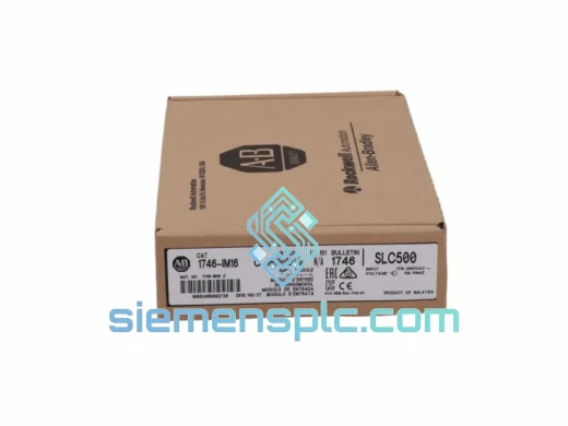
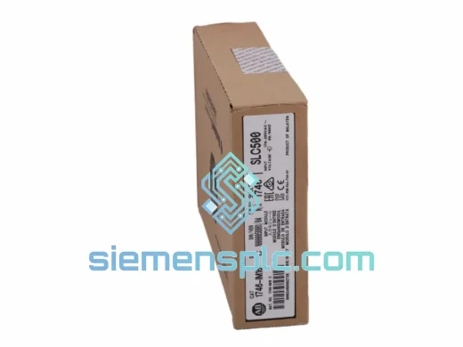
Allen-Bradley DIM16 Discrete Input Module
SLC 500
Origin US
Discrete Input Module
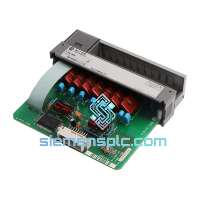
Request verified availability, condition, replacement risk review, packing options and courier lead time for 1746-IM8.
Click Request Quote and the part number is inserted into the inquiry form automatically.
Core fields for model confirmation and RFQ routing. Detailed product narrative remains below.
The Allen-Bradley 1746-IM8 is a discrete input module rated for 100–240V AC field signals, designed to occupy the signal acquisition layer within an SLC 500 modular control rack. Its functional mandate is precise: receive binary state information from AC-powered field devices — motor starter auxiliary contacts, limit switches, selector switches, and proximity sensors with AC output stages — and deliver a stable, optically isolated logic representation of each channel state to the SLC 500 processor’s input image table on every scan cycle.
The module handles eight independent input points, each galvanically isolated from the backplane at 1500V AC. This isolation architecture is not incidental; it is the primary mechanism by which the SLC 500 processor is protected from the electrical environment of a 240V AC field wiring system, where ground potential differences, inductive kickback from contactor coils, and common-mode transients are routine operating conditions rather than fault scenarios.
Signal conditioning on each channel follows a fixed hardware path: full-wave bridge rectification converts the AC input to pulsating DC, an RC filter network attenuates high-frequency conducted interference and smooths the rectified waveform, and a dedicated optocoupler translates the conditioned signal into a 5V DC logic level referenced to the backplane supply. The ON-state threshold is defined at 74V AC minimum; the OFF-state ceiling is 20V AC maximum. The 54V discrimination window between these thresholds is deliberately wide to prevent false triggering from capacitive leakage on long cable runs — a common failure mode in 240V AC installations with cable lengths exceeding 80 meters.
Within the SLC 500 scan cycle, input states are latched at the beginning of the input scan phase and held constant through the program scan and output scan phases. This deterministic latching behavior ensures that all ladder logic rungs referencing a given input bit operate on the same physical state within a single scan, eliminating the class of race conditions that arise when input hardware updates asynchronously with program execution.
Real-time Stock & RFQ: [email protected] | WhatsApp: +86 18359268345
| Parameter | Specification |
|---|---|
| Catalog Number | 1746-IM8 |
| Platform Compatibility | Allen-Bradley SLC 500 (all chassis sizes: 4, 7, 10, 13 slot) |
| Module Classification | Discrete Input — AC Voltage Type |
| Number of Input Points | 8, individually optocoupler-isolated |
| Nominal Input Voltage Range | 100–240V AC, 50/60 Hz |
| ON-State Voltage Threshold (min) | 74V AC |
| OFF-State Voltage Ceiling (max) | 20V AC |
| Input Current @ 120V AC, 60 Hz | 10 mA typical |
| Input Current @ 240V AC, 60 Hz | 5 mA typical |
| Input Impedance | 12 kΩ @ 60 Hz |
| Field-to-Backplane Isolation | 1500V AC, 50/60 Hz, 1 minute withstand |
| Input Filter Delay (ON transition) | 8–16 ms (hardware RC + processor filter) |
| Input Filter Delay (OFF transition) | 8–16 ms |
| Backplane Current Consumption | 75 mA @ 5V DC |
| Operating Temperature | 0°C to +60°C |
| Storage Temperature | −40°C to +85°C |
| Relative Humidity | 5–95%, non-condensing |
| Enclosure / Mounting | IP20, open-style, SLC 500 chassis slot |
| Approvals | UL Listed, CSA Certified, CE Marked, C-Tick |
| IEC Compliance | IEC 61131-2 Type 2 AC Input |
| Warranty | 12 months against manufacturing defects |
AC Signal Conditioning Chain: Each input channel processes the incoming AC field voltage through a four-stage hardware chain. Stage one is a transient voltage suppressor (TVS) at the terminal block, clamping inductive kickback spikes from contactor coils to a safe level before they reach the rectifier. Stage two is a full-wave bridge rectifier, converting the 50/60 Hz sinusoidal input into a pulsating DC waveform. Stage three is an RC filter network with a time constant matched to the input frequency, simultaneously smoothing the rectified waveform and attenuating conducted EMI above approximately 1 kHz — the frequency range where variable-frequency drives (VFDs) and switched-mode power supplies generate the most significant interference in industrial panel environments. Stage four is the optocoupler, which provides the galvanic isolation barrier and converts the conditioned analog level into a binary logic output.
Optocoupler Isolation Barrier: The 1500V AC withstand rating of the isolation barrier exceeds the IEC 61131-2 Type 2 minimum of 1000V AC by 50%. In practical terms, this margin accommodates the transient overvoltages that occur during contactor switching in 240V AC systems — events that can produce voltage spikes of 2–4× the nominal line voltage on the field wiring, depending on cable inductance and the absence of arc suppression on the contactor coil. The phototransistor output is referenced to the 5V DC backplane supply, ensuring that the logic signal presented to the backplane data bus is fully compatible with the SLC 500 processor’s input image table read cycle.
ON/OFF Discrimination Window Engineering: The 54V gap between the 20V AC OFF ceiling and the 74V AC ON floor is a deliberate design parameter, not a manufacturing tolerance. In a 240V AC system, the capacitive leakage current through a 100-meter cable run can sustain 10–15V AC on an open input terminal. The 20V AC OFF ceiling provides a 5–10V margin above this leakage level, preventing false ON states from cable capacitance alone. Engineers specifying this module for installations with cable runs approaching 150 meters should calculate the expected leakage voltage using the cable’s capacitance-per-meter specification and verify it remains below 18V AC to maintain a 2V safety margin.
Electronic Keying and Configuration Integrity: At power-up, the SLC 500 processor reads the module’s identity data — catalog number, series letter, and firmware revision — from the backplane and compares it against the I/O configuration stored in processor file N7. A mismatch generates a Major Fault Type 3 (I/O configuration mismatch), halting the processor and preventing program execution. This hardware-enforced keying mechanism eliminates the risk of silent module substitution — a failure mode where an incorrect module type is installed without triggering a fault, allowing the program to execute with incorrect I/O mapping.
PCB Layout and EMC Creepage/Clearance: The module’s PCB maintains creepage and clearance distances per IEC 60664-1 for 300V AC working voltage, Pollution Degree 2, Installation Category II. The high-voltage field-side traces are physically separated from the backplane-side logic traces by the isolation barrier, with no shared ground plane crossing the barrier. The chassis PE connection provides a low-impedance return path for common-mode noise currents, reducing the susceptibility of adjacent modules in the rack to conducted interference from the 1746-IM8’s field wiring.
Each 1746-IM8 unit supplied through siemensplc.com undergoes a structured pre-shipment inspection before dispatch from our Xiamen, China facility. Physical authenticity verification cross-references Rockwell Automation holographic labels, PCB date codes, series letter markings, and terminal block construction against documented reference specifications for genuine units. This step is mandatory given the volume of remarked and refurbished SLC 500 modules circulating in the surplus market.
Functional testing uses a reference SLC 500 chassis with a known-good processor. Each of the eight input channels is exercised through ON and OFF state transitions using a calibrated AC source at both 120V and 240V. Backplane communication is verified by confirming that the processor reads the correct module identity data and maps the input states correctly to the I/O image table. Isolation resistance between field terminals and the backplane connector is measured and must exceed the minimum specification before the unit is accepted for shipment.
Units pass inspection are packed in anti-static (ESD) bags, placed in rigid foam-lined cartons, and labeled with catalog number, series, and inspection date. A certificate of conformance accompanies every shipment. IEC-format test reports are available upon request for quality-critical procurement processes.
Logistics from Xiamen, China covers DHL Express, FedEx International Priority, and UPS Worldwide Expedited. Standard transit times: 3–5 business days to Europe, 2–4 business days to Southeast Asia, 4–6 business days to North America. Export documentation — commercial invoice, packing list, certificate of origin — is prepared for every international order. HS code 8537.10 applies. Orders confirmed before 14:00 CST qualify for same-day dispatch. A 12-month warranty with a replacement-first policy covers all units against manufacturing defects under normal operating conditions.
📧 Email: [email protected]
📱 WhatsApp: +86 18359268345
🌐 Web: siemensplc.com
📍 Location: Xiamen, China
© 2026 siemensplc.com. All rights reserved.
We check the full part number, brand, series and visible nameplate information before quotation.
Sales confirms stock path, condition option, quantity and realistic lead time for export dispatch.
DHL, FedEx, UPS or buyer courier arrangements can be reviewed with packing requirements.
Similar brand or category products for fast comparison and multi-item RFQ lists.