Allen-Bradley
RFQ Ready
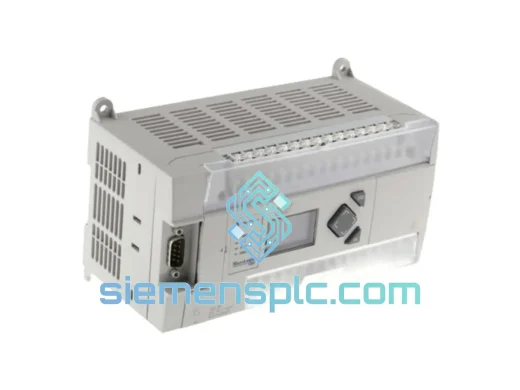
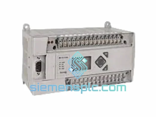
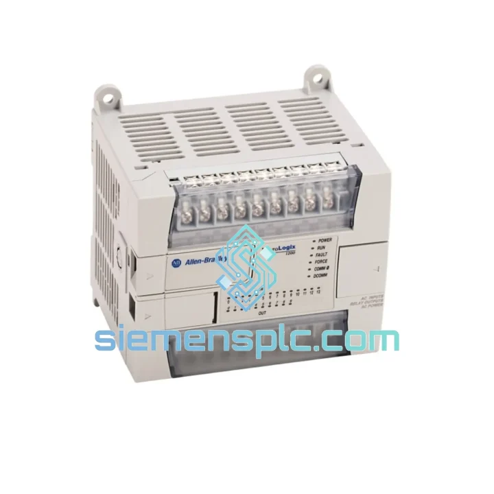
Allen-Bradley 1766-L32BXBA PLC Controller
MicroLogix
Origin US
PLC Controller
Request verified availability, condition, replacement risk review, packing options and courier lead time for 1763-L16DWD.
Click Request Quote and the part number is inserted into the inquiry form automatically.
Core fields for model confirmation and RFQ routing. Detailed product narrative remains below.
The 1763-L16DWD is a 16-point programmable controller within Rockwell Automation’s MicroLogix 1100 family. It integrates 10 × 24V DC sinking/sourcing digital inputs, 6 relay outputs rated at 2 A per point, two onboard analog inputs (0–10 V DC or 4–20 mA), one analog output (0–10 V DC or 4–20 mA), a native 10/100 Mbps EtherNet/IP port, and a dual-port serial interface — all within a 90 × 130 × 87 mm DIN-rail housing drawing 350 mA at 24 V DC. This architecture positions the unit as a self-contained node capable of handling closed-loop analog regulation, high-speed pulse counting, and Ethernet-based supervisory communication without any expansion module for the majority of small-machine applications.
The controller executes ladder logic, function block diagram (FBD), and structured text programs stored across 8 KB of program memory and 8 KB of data memory, both battery-backed to retain state through power interruptions. A 4-line × 20-character backlit LCD with four navigation keys provides local operator interaction — displaying custom messages, fault codes, and data values — eliminating the need for a dedicated HMI panel in single-operator installations. Scan time is deterministic at sub-millisecond rates for typical 16-point programs, making the unit suitable for time-critical interlock and sequencing logic.
Real-time Stock & RFQ: [email protected] | WhatsApp: +86 18359268345
| Catalog Number | 1763-L16DWD |
| Platform / Series | MicroLogix 1100 |
| Manufacturer | Allen-Bradley / Rockwell Automation |
| Country of Origin | United States |
| Total I/O Points | 16 (10 DI + 6 DO) |
| Digital Inputs | 10 × 24V DC, sink/source configurable, IEC Type 1 |
| Input Voltage Range | ON state: 15–26.4 V DC; OFF state: 0–5 V DC |
| Input Filter Time | 1 ms (configurable 0–32 ms per point) |
| Digital Outputs | 6 × Relay, Form A (SPST-NO), 2 A @ 240 V AC / 30 V DC |
| Output Surge Rating | 7.5 A for 10 ms (inductive load) |
| Relay Mechanical Life | 10 million operations (no load) |
| Analog Inputs | 2 × 12-bit, 0–10 V DC or 4–20 mA (software selectable) |
| Analog Output | 1 × 12-bit, 0–10 V DC or 4–20 mA (software selectable) |
| Analog Resolution | 12-bit (4096 counts full scale) |
| High-Speed Counter | Up to 20 kHz single-phase; 8 kHz quadrature (A/B encoder) |
| PTO / PWM | Yes — pulse train output and pulse-width modulation via dedicated output |
| Power Supply Input | 24 V DC (operating range: 19.2–26.4 V DC) |
| Current Consumption | 350 mA typical at 24 V DC |
| Program Memory | 8 KB (battery-backed SRAM) |
| Data Memory | 8 KB (battery-backed SRAM) |
| Communication Port 1 | RS-232 / RS-485 combo (DH-485, DF1 full/half-duplex, ASCII, Modbus RTU) |
| Communication Port 2 | 10/100 Mbps EtherNet/IP (RJ-45) — EtherNet/IP, Modbus TCP, SMTP |
| Real-Time Clock | Battery-backed, ±2 min/month accuracy |
| LCD Display | 4-line × 20-character backlit LCD + 4 navigation keys |
| Operating Temperature | 0 °C to +60 °C (horizontal mount); 0 °C to +55 °C (vertical mount) |
| Storage Temperature | −40 °C to +85 °C |
| Relative Humidity | 5–95% non-condensing |
| Vibration Resistance | 2 g @ 10–500 Hz (IEC 60068-2-6) |
| Shock Resistance | 15 g, 11 ms half-sine (IEC 60068-2-27) |
| Enclosure Rating | IP20 (panel-mount installation required) |
| Mounting | 35 mm DIN rail (EN 50022) or panel surface mount |
| Dimensions (H × W × D) | 90 × 130 × 87 mm |
| Weight | 650 g (approx.) |
| Programming Software | RSLogix 500 v8.10+ (Ladder, FBD, SFC, Structured Text) |
| Firmware Upgrade | Field-upgradeable via EtherNet/IP — no physical access required |
| Certifications | UL 508, CE (EN 61131-2), C-Tick, RoHS 2011/65/EU |
| Warranty | 12 months from date of shipment |
The 1763-L16DWD’s digital input stage employs optical isolation between the field-side 24 V DC signal and the controller’s internal 5 V DC logic bus. Each input channel passes through a current-limiting resistor network before reaching the opto-coupler, establishing a galvanic barrier rated to withstand transient voltages up to 1500 V AC for 1 minute per IEC 61131-2. This isolation architecture prevents ground loops from propagating into the CPU’s data bus — a critical design requirement in motor-drive environments where common-mode noise on the 24 V DC rail can reach several hundred millivolts.
The relay output stage uses Form A (SPST-NO) electromechanical relays with a rated mechanical life of 10 million operations under no-load conditions. Each relay coil is driven by a dedicated transistor driver with a flyback diode across the coil to suppress the inductive kick at de-energization — protecting the output driver IC from voltage spikes that would otherwise exceed its breakdown rating. The relay contacts are rated at 2 A resistive at 240 V AC, with a surge capability of 7.5 A for 10 ms to handle the inrush current of contactor coils and solenoid valves without contact welding.
The onboard analog subsystem uses a 12-bit successive-approximation ADC (SAR-ADC) shared across the two analog input channels via a multiplexed front end. Conversion time per channel is approximately 250 µs, yielding a total analog scan contribution of 500 µs for both channels — a figure that must be factored into the overall program scan time budget for closed-loop PID applications. The analog output uses a 12-bit DAC with a buffered voltage output stage capable of driving loads down to 1 kΩ (10 V / 10 mA) or a current loop transmitter in 4–20 mA mode. Both input and output channels are software-configurable between voltage and current modes, eliminating the need for hardware jumpers.
The high-speed counter (HSC) module operates independently of the main ladder scan, using a dedicated hardware counter register clocked directly from the input terminal. This hardware-level counting ensures no pulse is missed regardless of the current scan time — a fundamental requirement when interfacing with incremental encoders on conveyor drives or flow meters with pulse outputs up to 20 kHz. The HSC supports four operating modes: accumulator, period measurement, rate measurement, and quadrature (A/B phase) for bidirectional position tracking.
EMC performance is achieved through a combination of design measures: the internal 5 V DC logic power supply uses a switching regulator with spread-spectrum frequency modulation to reduce conducted emissions; the PCB layout routes high-frequency clock signals on inner layers with ground plane shielding; and all I/O terminals are filtered with RC networks to attenuate high-frequency transients before they reach the logic circuitry. The unit meets EN 61000-4-4 (EFT/Burst, 2 kV) and EN 61000-4-5 (Surge, 1 kV line-to-line) immunity levels.
Every 1763-L16DWD unit supplied by siemensplc.com is sourced through documented industrial supply channels and subjected to a structured pre-shipment verification process before dispatch from our Xiamen, China facility.
Pre-shipment inspection protocol:
Logistics: Orders are dispatched from Xiamen, China within 1–3 business days of payment confirmation. Express freight options include DHL Express, FedEx International Priority, and UPS Worldwide Express — with typical transit times of 3–5 business days to Europe, North America, Southeast Asia, and the Middle East. Tracking numbers are provided via email at the time of dispatch. For time-critical procurement, same-day dispatch is available for orders confirmed before 14:00 CST.
Warranty: All units carry a 12-month warranty from the date of shipment. Dead-on-arrival (DOA) units are eligible for replacement within 7 days of confirmed receipt. Warranty claims are processed via email with photographic evidence of the defect; replacement units are dispatched within 2 business days of claim approval.
Email: [email protected]
WhatsApp: +86 18359268345
Web: siemensplc.com
Location: Xiamen, China
© 2026 siemensplc.com. All rights reserved.
We check the full part number, brand, series and visible nameplate information before quotation.
Sales confirms stock path, condition option, quantity and realistic lead time for export dispatch.
DHL, FedEx, UPS or buyer courier arrangements can be reviewed with packing requirements.
Similar brand or category products for fast comparison and multi-item RFQ lists.