Allen-Bradley
RFQ Ready
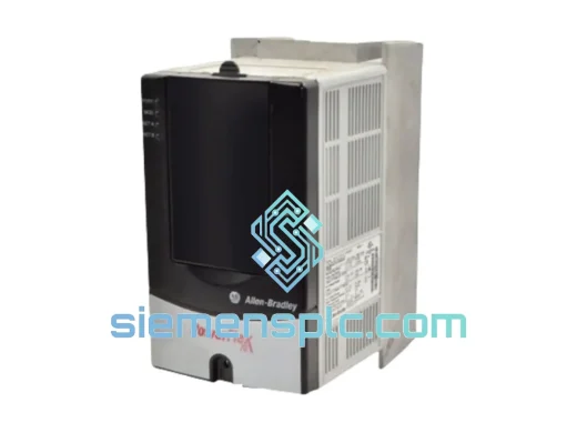
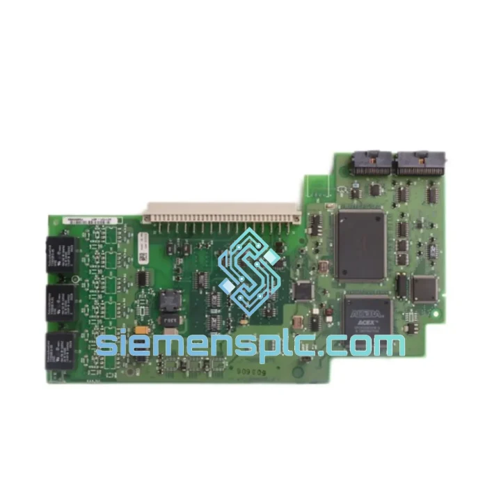
Allen-Bradley 20AD3P4A0AYNNNC0 Variable Frequency Drive
PowerFlex
Origin US
Variable Frequency Drive
Request verified availability, condition, replacement risk review, packing options and courier lead time for 321131-A01.
Click Request Quote and the part number is inserted into the inquiry form automatically.
Core fields for model confirmation and RFQ routing. Detailed product narrative remains below.
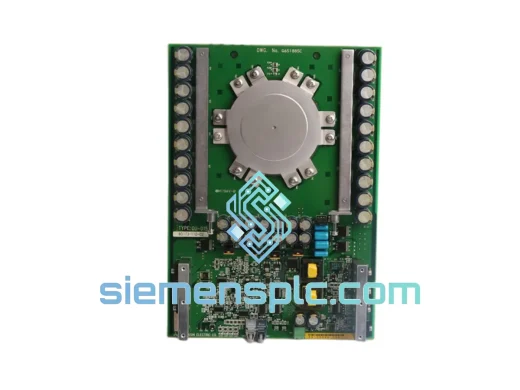
The Allen-Bradley 321131-A01 is the main inverter control PCB used within the PowerFlex family of AC variable-frequency drives manufactured by Rockwell Automation. Its primary function is to execute the pulse-width modulation (PWM) switching sequence that governs IGBT gate firing in the inverter bridge stage, translating DC bus voltage into a synthesized three-phase AC output with programmable frequency and amplitude. The board integrates the motor control algorithm processor, analog signal conditioning circuitry, and the drive’s internal communication backbone into a single replaceable assembly — making it the functional core of the drive’s closed-loop speed and torque regulation.
In a standard PowerFlex drive topology, the 321131-A01 receives feedback from the DC bus voltage sensor, output current transducers, and optional encoder or resolver inputs. It processes these signals through its onboard DSP to compute real-time slip compensation, flux vector correction, or sensorless vector estimates depending on the configured control mode. The resulting gate signals are transmitted to the gate driver board via a high-speed fiber-optic or direct-coupled interface, maintaining electrical isolation between the low-voltage control domain and the high-voltage power stage.
Procurement engineers and maintenance teams sourcing this board should note that the 321131-A01 carries a specific hardware revision suffix (A01) that determines firmware compatibility. Substituting a different revision without verifying the drive’s firmware baseline can result in parameter incompatibility or fault codes at startup. siemensplc.com technical staff can assist with revision cross-referencing prior to order confirmation.
Real-time Stock & RFQ: [email protected] | WhatsApp: +86 18359268345
| Parameter | Specification |
|---|---|
| Part Number | 321131-A01 |
| Hardware Revision | A01 |
| Manufacturer | Allen-Bradley / Rockwell Automation |
| Component Classification | Inverter Main Control PCB |
| Compatible Drive Family | PowerFlex Series AC Drives |
| Control Voltage (Logic Supply) | +5 VDC / +15 VDC (internal SMPS regulated) |
| PWM Carrier Frequency Range | 2 kHz – 16 kHz (drive-model dependent) |
| Processor Architecture | Fixed-point DSP with dedicated motor control peripherals |
| Communication Interface | Internal backplane bus; optional DPI / EtherNet/IP adapter port |
| Analog Input Resolution | 12-bit ADC (current and voltage feedback channels) |
| Operating Temperature | 0 °C to +50 °C (ambient, drive enclosure rated) |
| Storage Temperature | -40 °C to +85 °C |
| Humidity (Non-condensing) | 5% – 95% RH |
| PCB Dimensions | Refer to PowerFlex drive service manual for chassis-specific fit |
| Net Weight | Approx. 180 g |
| Country of Origin | United States of America |
| Condition Available | New / Surplus New / Tested Refurbished |
| Warranty | 12 months from date of shipment |
The 321131-A01 board design reflects Rockwell Automation’s approach to separating control-domain logic from power-domain switching noise through deliberate PCB layer stackup and signal routing discipline. The analog feedback traces — carrying millivolt-level current transducer outputs — are routed on inner copper layers shielded by ground planes on both adjacent layers, reducing capacitive coupling from the high-dV/dt switching transients present on the gate driver interconnect. This layout practice directly reduces common-mode noise injection into the ADC input stage, which would otherwise manifest as speed ripple or spurious overcurrent faults at high PWM carrier frequencies.
The gate signal output path from the DSP to the fiber-optic transmitter (where applicable) uses differential signaling with matched trace lengths to minimize skew between the six PWM channels. Skew beyond approximately 50 ns in a three-phase bridge can produce asymmetric dead-time insertion, leading to DC offset in the output current waveform and increased motor heating at low speeds. The board’s hardware dead-time enforcement circuit operates independently of the DSP, providing a fail-safe floor that prevents shoot-through even if firmware generates overlapping gate commands during a fault recovery sequence.
EMC compliance is addressed at the board level through ferrite bead filtering on all inter-board connector pins, transient voltage suppression (TVS) diodes on the analog input lines, and a dedicated chassis ground stitch capacitor array that provides a low-impedance return path for high-frequency common-mode currents. These measures allow the drive to meet EN 61800-3 Category C2 conducted and radiated emission limits without requiring additional external filtering in most standard industrial installations.
The onboard EEPROM stores drive configuration parameters and fault history. During a board replacement, parameter migration via the HIM module or DriveExecutive software is required to restore the previous operating configuration — a step that is frequently overlooked in field replacements and results in incorrect motor nameplate data being applied to the new board’s default parameter set.
Every 321131-A01 unit dispatched by siemensplc.com is sourced through documented industrial distribution channels with full traceability to manufacturer date codes and lot records. Incoming units are inspected against a defined acceptance checklist covering PCB surface condition, connector pin integrity, component marking authenticity, and revision label verification. Units that exhibit evidence of rework, re-marking, or non-original solder joints are rejected at intake and do not enter saleable stock.
For units designated as tested refurbished, a functional verification procedure is performed using a compatible PowerFlex drive chassis with a known-good motor load. The test sequence exercises the board across multiple control modes, verifies analog I/O calibration, and confirms fault logging function. A test record is retained and available to the buyer upon request.
Logistics operations are based in Xiamen, China, with access to DHL Express, FedEx International Priority, and EMS international postal services. In-stock orders are processed and handed to the carrier within 1–3 business days. Full export documentation — commercial invoice, packing list, Certificate of Origin, and HS code declaration — is prepared for each shipment to support customs clearance in the destination country. Bulk order pricing and consolidated freight arrangements are available for procurement quantities of five units or more.
📧 Email: [email protected]
📱 WhatsApp: +86 18359268345
🌐 Web: siemensplc.com
📍 Location: Xiamen, China
© 2026 siemensplc.com. All rights reserved.
We check the full part number, brand, series and visible nameplate information before quotation.
Sales confirms stock path, condition option, quantity and realistic lead time for export dispatch.
DHL, FedEx, UPS or buyer courier arrangements can be reviewed with packing requirements.
Similar brand or category products for fast comparison and multi-item RFQ lists.