Mitsubishi Electric
RFQ Ready
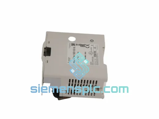
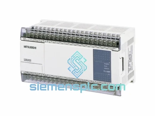
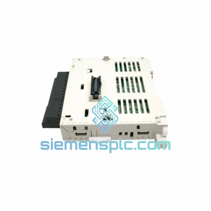
Mitsubishi FX3U-4AD-PT-ADP Analog Input Adapter
MELSEC FX
Origin JP
PLC Analog Input Adapter
Request verified availability, condition, replacement risk review, packing options and courier lead time for FX3U-4DA.
Click Request Quote and the part number is inserted into the inquiry form automatically.
Core fields for model confirmation and RFQ routing. Detailed product narrative remains below.
The Mitsubishi FX3U-4DA is a dedicated 4-channel analog output special function module engineered for the MELSEC FX3U and FX3UC programmable controller families. Its primary function within a control loop is digital-to-analog conversion: it receives 16-bit signed integer data written by the FX3U CPU into designated buffer memory registers and translates those values into calibrated analog voltage or current signals that drive field actuators — variable frequency drives, proportional control valves, electro-pneumatic positioners, and process controllers. Each of the four channels operates independently, allowing simultaneous multi-axis or multi-loop analog output from a single compact module occupying one expansion slot on the FX3U right-side bus.
In closed-loop process control, the FX3U-4DA sits at the output boundary of the control chain. The CPU executes the PID or custom control algorithm, computes the manipulated variable, and writes the result to the module’s buffer memory via TO instructions (or direct buffer access in GX Works2). The FX3U-4DA then performs the D/A conversion and drives the analog output terminal within 1 ms per channel — a 4 ms total scan contribution that is deterministic and compatible with the FX3U’s standard 0.065 µs instruction cycle. This tight timing relationship ensures that analog output updates remain synchronized with the CPU scan cycle, which is a prerequisite for stable proportional control in fast-response applications such as tension regulation and servo feed-forward compensation.
Real-time Stock & RFQ: [email protected] | WhatsApp: +86 18359268345
| Parameter | Specification |
|---|---|
| Model Number | FX3U-4DA |
| Manufacturer | Mitsubishi Electric |
| Compatible PLC Series | MELSEC FX3U, FX3UC |
| Number of Output Channels | 4 (fully independent) |
| Voltage Output Range | −10 VDC to +10 VDC |
| Current Output Range | 4 mA to 20 mA DC |
| D/A Resolution – Voltage | 12-bit (1/4096 of full scale) |
| D/A Resolution – Current | 11-bit (1/2048 of full scale) |
| Conversion Speed | 1 ms per channel (4 ms for all 4 channels) |
| Absolute Accuracy (25 °C) | ±0.5% of full scale (voltage); ±0.5% of full scale (current) |
| Temperature Coefficient | ±0.05% FS / 10 °C |
| Load Resistance – Voltage | ≥ 2 kΩ |
| Load Resistance – Current | ≤ 600 Ω |
| Isolation Method | Optocoupler (between CPU bus and analog output circuits) |
| Internal Power (from PLC bus) | 5 VDC, 90 mA |
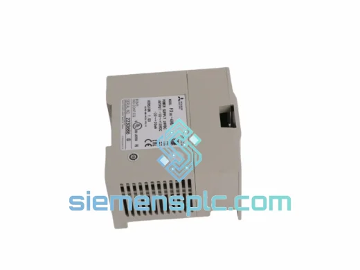
| External Power Supply Required | 24 VDC ±10%, 60 mA |
| Operating Temperature | 0 °C to +55 °C |
| Storage Temperature | −25 °C to +75 °C |
| Relative Humidity | 5% to 95% RH (non-condensing) |
| Vibration Resistance | 5 to 9 Hz: 3.5 mm amplitude; 9 to 150 Hz: 9.8 m/s² |
| Shock Resistance | 147 m/s², 3 axes |
| Dimensions (W × H × D) | 55 mm × 90 mm × 87 mm |
| Weight | Approx. 200 g |
| Max. Special Function Modules per CPU | 8 modules |
| Certifications | CE, UL |
| Warranty | 12 months against manufacturing defects |
| Country of Origin | Japan |
The FX3U-4DA’s internal architecture is structured around a dedicated D/A converter ASIC per channel pair, with each converter clocked independently to prevent inter-channel crosstalk during simultaneous update cycles. The digital input side of each converter is latched from the FX3U expansion bus via a 16-bit parallel interface; the latch is triggered by the TO instruction execution in the CPU scan, ensuring that all four output values are captured atomically within a single bus transaction window.
Optocoupler Isolation Architecture: The galvanic barrier between the 5 VDC logic domain (PLC bus side) and the 24 VDC analog output domain is implemented using high-speed optocouplers rated for ≥ 500 VDC isolation voltage. This barrier serves two functions: it prevents ground loop currents — common in industrial panels where multiple field devices share a common analog reference — from corrupting the digital logic supply, and it attenuates common-mode noise injected by long cable runs to actuators. In environments with variable frequency drives operating at switching frequencies of 2–16 kHz, this isolation is the primary defense against conducted EMI reaching the CPU backplane.
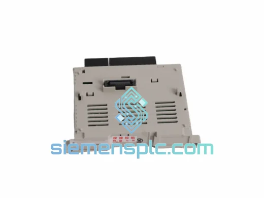
EMC Design: The PCB layout routes analog output traces on a dedicated copper pour separated from the digital signal layer by a ground plane. Output terminals are filtered with RC networks tuned to attenuate frequencies above 10 kHz, which corresponds to the lower bound of typical VFD switching harmonics. The module’s metal housing provides additional shielding against radiated emissions, and the DIN rail mounting clip establishes a low-impedance chassis ground path that completes the EMC enclosure.
Output Drive Capability: The voltage output stage uses a rail-to-rail operational amplifier topology capable of sourcing or sinking up to 5 mA into a minimum 2 kΩ load. The current output stage employs a precision voltage-to-current converter with a compliance voltage headroom of approximately 12 V, allowing it to drive loads up to 600 Ω at 20 mA without output saturation. Both output types include short-circuit protection circuitry that limits fault current and generates a diagnostic flag in buffer memory register BFM #28 (error status word), which the CPU can poll via FROM instructions to implement fault-tolerant control logic.
Buffer Memory Map: Each channel occupies four consecutive buffer memory words: output data (BFM #0–3), output mode selection (BFM #16–19), output enable flags (BFM #20), and error status (BFM #28). This flat memory structure allows GX Works2 to configure all channel parameters through a single structured data block write, reducing commissioning time compared to modules requiring multi-step initialization sequences.
Every FX3U-4DA unit supplied by siemensplc.com is sourced through verified Mitsubishi Electric authorized distribution channels. Each module carries the original Mitsubishi Electric holographic authenticity label and is accompanied by a traceable lot number that can be cross-referenced against Mitsubishi Electric’s production records. Units are not repackaged or relabeled; original OEM cartons are preserved where available, and anti-static foam inserts protect the module’s analog output terminals and bus connector during transit.
Prior to dispatch, each unit undergoes a functional verification check: the module is powered via a 24 VDC bench supply, connected to an FX3U test CPU, and all four analog output channels are exercised across their full output range. Voltage output linearity is verified at 0%, 50%, and 100% of full scale; current output compliance is confirmed at 4 mA and 20 mA endpoints. Units that do not meet Mitsubishi Electric’s published accuracy specifications are quarantined and returned to the supplier — they are not offered for sale.
Shipments originate from our warehouse in Xiamen, China (Fujian Province), a major logistics hub with direct access to Xiamen Gaoqi International Airport and Xiamen Port. Standard international shipments are dispatched via DHL Express, FedEx International Priority, or UPS Worldwide Expedited, with transit times of 3–7 business days to most destinations in Europe, North America, Southeast Asia, and the Middle East. For time-critical orders, same-day dispatch is available for in-stock units ordered before 14:00 CST. All export shipments include a commercial invoice, packing list, and certificate of origin; CITES and dual-use export compliance documentation is available upon request for regulated destinations.
A 12-month warranty against manufacturing defects is provided on all units. Warranty claims are processed within 5 business days of receipt of the returned unit; replacement units are dispatched from Xiamen stock. Extended 24-month warranty coverage is available for volume orders exceeding 10 units — contact us for terms.
Email: [email protected]
WhatsApp: +86 18359268345
Web: siemensplc.com
Location: Xiamen, China
© 2026 siemensplc.com. All rights reserved.
We check the full part number, brand, series and visible nameplate information before quotation.
Sales confirms stock path, condition option, quantity and realistic lead time for export dispatch.
DHL, FedEx, UPS or buyer courier arrangements can be reviewed with packing requirements.
Similar brand or category products for fast comparison and multi-item RFQ lists.