Mitsubishi Electric
RFQ Ready
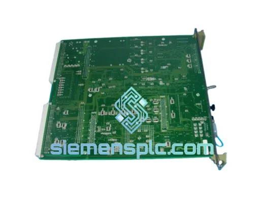
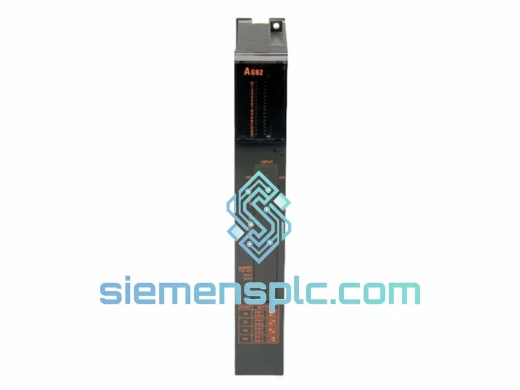
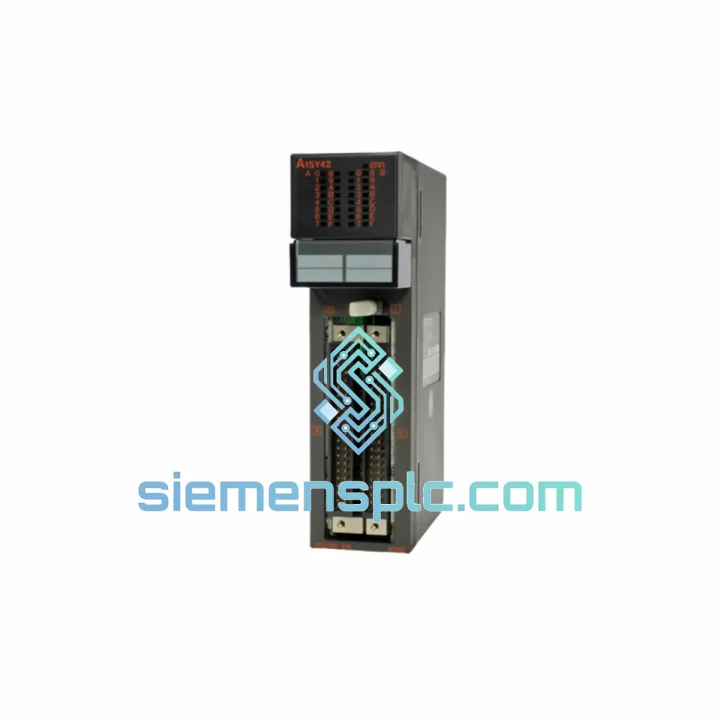
Mitsubishi Electric DOIOC11 DCS Digital Output Module
MELSEC-A
Origin JP
DCS Digital Output Module
Request verified availability, condition, replacement risk review, packing options and courier lead time for MELSEC-A.
Click Request Quote and the part number is inserted into the inquiry form automatically.
Core fields for model confirmation and RFQ routing. Detailed product narrative remains below.
The A1SY42 is a 16-channel sink-type (NPN) transistor output module designed for the Mitsubishi MELSEC-A AnS-series programmable logic controller platform. Within a discrete control loop, this module occupies the final execution layer: it receives output commands from the CPU via the backplane bus, drives the photocoupler isolation stage, and switches the external field-side load circuit at sub-millisecond response times. Each output channel is independently controlled, allowing the CPU to assert or de-assert any combination of the 16 points within a single scan cycle without inter-channel dependency.
In process terms, the A1SY42 translates the CPU’s binary register state into physical switching events — energizing solenoid valves, relay coils, indicator lamps, and low-power actuators operating on 12–24 VDC field power. The module does not source current; it provides a switched path to the common negative rail (NPN/sink topology), which is the standard wiring convention for the majority of Asian-market field devices and Mitsubishi-native I/O ecosystems.
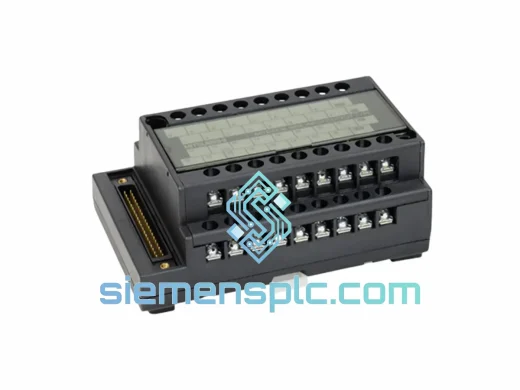
The module slots directly into any AnS-series slim base unit (A1S33B, A1S35B, A1S38B, A1S52B, A1S55B, A1S58B) and communicates with the CPU over the internal backplane bus at the base unit’s native cycle rate. No additional interface cards, protocol converters, or external power conditioning are required beyond the field-side 12–24 VDC supply. The 40-pin connector (A6CON1/A6CON2 compatible) provides a high-density wiring interface that supports both crimp-type and solder-type termination, accommodating panel wiring practices across different regional standards.
Real-time Stock & RFQ: [email protected] | WhatsApp: +86 18359268345
| Part Number | A1SY42 |
| Manufacturer | Mitsubishi Electric |
| Series | MELSEC-A / AnS Slim Series |
| Module Classification | Digital Transistor Output Module |
| Output Points | 16 points |
| Output Topology | NPN (Sink-type), Open Collector Transistor |
| Rated Load Voltage | 12–24 VDC |
| Max Load Current per Point | 0.1 A |
| Max Aggregate Load Current | 1.6 A (all 16 points simultaneously ON) |
| Leakage Current (OFF State) | ≤ 0.1 mA |
| Residual Voltage (ON State) | ≤ 1.5 V |
| Isolation Method | Photocoupler (optical isolation, logic ↔ field) |
| Response Time OFF→ON | ≤ 1 ms |
| Response Time ON→OFF | ≤ 1 ms |
| External Supply Voltage | 12–24 VDC (field-side, externally supplied) |
| Internal Current Consumption (5 VDC bus) | 90 mA (from base unit backplane) |
| Connector Type | 40-pin (A6CON1 crimp / A6CON2 solder) |
| Compatible Base Units | A1S33B, A1S35B, A1S38B, A1S52B, A1S55B, A1S58B |
| Operating Temperature | 0 °C to +55 °C |
| Storage Temperature | −25 °C to +75 °C |
| Relative Humidity | 5–95% RH, non-condensing |
| Vibration Resistance | 10–57 Hz: 0.075 mm amplitude; 57–150 Hz: 9.8 m/s² |
| Shock Resistance | 147 m/s², 3 axes |
| Dielectric Withstand Voltage | 500 VAC, 1 minute (between external terminals and ground) |
| Insulation Resistance | ≥ 10 MΩ at 500 VDC |
| Module Weight | Approx. 260 g |
| Applicable Standards | CE (EMC 2014/30/EU, LVD 2014/35/EU), UL 508, IEC 61131-2, RoHS |
| Warranty | 12 months from date of shipment |
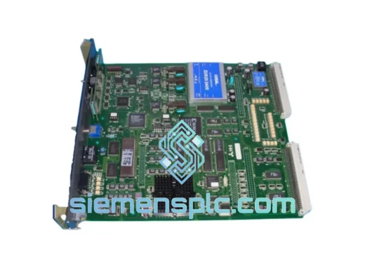
The A1SY42’s output stage is built around a discrete NPN transistor array driven by photocoupler isolation elements — one per channel. When the CPU writes a logic-1 to the corresponding output register bit, the LED side of the photocoupler conducts, activating the phototransistor, which in turn saturates the output NPN transistor and closes the load circuit to the COM terminal (negative rail). This two-stage switching architecture — photocoupler followed by power transistor — provides two distinct functional benefits.
First, the photocoupler establishes a galvanic barrier rated at 500 VAC between the 5 VDC logic domain (backplane bus) and the 12–24 VDC field domain. Transient voltages induced by inductive load switching — solenoid valve coil collapse, relay de-energization — are absorbed by the field-side suppression network and cannot propagate back through the isolation barrier into the CPU’s data bus. This is the primary EMC defense mechanism of the module and the reason the A1SY42 can operate reliably in environments with significant electromagnetic interference from variable-frequency drives, welding equipment, and high-current contactors.
Second, the open-collector NPN output topology means the module does not generate its own field-side voltage. The external 12–24 VDC supply is wired by the user, and the module simply provides the switched return path. This architecture eliminates the risk of backfeed from the field supply into the PLC logic rail, and it allows the field supply voltage to be selected independently of the PLC’s internal power supply — a practical advantage when integrating with legacy 12 V field devices or when the field supply is derived from a UPS-backed rail separate from the control cabinet’s main supply.
The 40-pin connector interface distributes the 16 output channels across dedicated pins with a shared COM arrangement, allowing the wiring harness to be pre-fabricated and tested off-panel before installation. The connector’s mechanical keying prevents mis-insertion, and the locking latch maintains contact integrity under the vibration profiles specified in IEC 61131-2 (10–150 Hz, 9.8 m/s²).
The module’s internal 5 VDC consumption of 90 mA from the backplane is a fixed overhead that must be accounted for in base unit power budget calculations. When populating a multi-slot base unit with multiple A1SY42 modules, the aggregate 5 VDC draw must remain within the power supply module’s rated output (A1S61P: 6 A at 5 VDC; A1S62P: 3 A at 5 VDC). The field-side current (up to 1.6 A per module) is supplied entirely from the external 12–24 VDC source and does not load the backplane supply.
Every A1SY42 unit dispatched from our Xiamen, China facility is sourced from verified supply channels and subjected to a structured pre-shipment inspection protocol. Visual examination covers label authenticity, connector pin integrity, housing condition, and date-code consistency. Functional verification confirms that the module’s LED status indicators respond correctly to power application and that output channel continuity is within specification. Units are packaged in anti-static bags with desiccant and humidity indicator cards, then placed in rigid corrugated cartons with foam-cushion inserts rated for the IEC 61131-2 shock and vibration transport profile.
Export documentation — commercial invoice, packing list, certificate of origin, and HS code declaration (HS 8537.10) — is prepared for each shipment to facilitate customs clearance in the destination country. Shipments are dispatched via DHL Express, FedEx International Priority, and EMS, with typical transit times of 3–7 business days to major industrial hubs in Southeast Asia, the Middle East, Europe, and the Americas. For project orders requiring multiple line items or consolidated BOM fulfillment, consolidated shipment scheduling is available upon request. All units carry a 12-month warranty from the date of shipment, covering manufacturing defects and functional failures under normal operating conditions as defined in the Mitsubishi Electric product specification.
Email: [email protected]
WhatsApp: +86 18359268345
Web: siemensplc.com
Location: Xiamen, China
© 2026 siemensplc.com. All rights reserved.
We check the full part number, brand, series and visible nameplate information before quotation.
Sales confirms stock path, condition option, quantity and realistic lead time for export dispatch.
DHL, FedEx, UPS or buyer courier arrangements can be reviewed with packing requirements.
Similar brand or category products for fast comparison and multi-item RFQ lists.