Bently Nevada
RFQ Ready
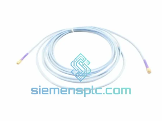
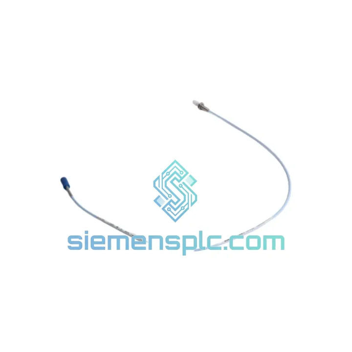
Bently Nevada 330730-080-02-00 Extension Cable
3300 Series
Origin US
Extension Cable
Request verified availability, condition, replacement risk review, packing options and courier lead time for 330901-00-32-05-02-05.
Click Request Quote and the part number is inserted into the inquiry form automatically.
Core fields for model confirmation and RFQ routing. Detailed product narrative remains below.
Your compressor train is running. The 3300 Series rack is powered. But the velocity channel is flatlined — and you have no idea whether that bearing is about to let go. A failed Velomitor transducer is not a paperwork problem. It is a live operational risk. The 330901-00-32-05-02-05 is the exact unit you need to restore full-spectrum casing velocity monitoring before your next scheduled window closes — or before the machine makes the decision for you.
We stock the Bently Nevada 330901-00-32-05-02-05 in Xiamen and ship globally via DHL and FedEx Express. No lead-time negotiation. No factory order queue. If it is on the shelf, it leaves within 24 hours of payment confirmation. That is the only promise that matters when your protection system has a hole in it.
⚡ URGENT REQUIREMENT? Contact: [email protected] | WhatsApp: +86 18359268345
| Parameter | Specification |
|---|---|
| Part Number | 330901-00-32-05-02-05 |
| Brand | Bently Nevada (Baker Hughes) |
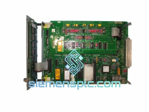
| Series | 3300 XY Series Machinery Protection System |
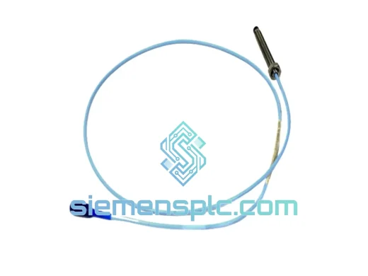
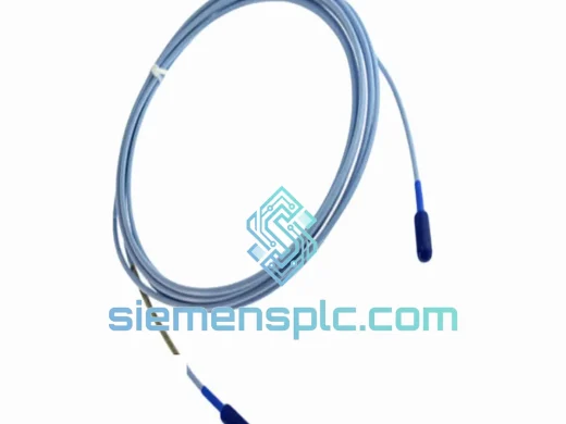
| Transducer Type | Velomitor — Piezoelectric Velocity Transducer |
| Measurement | Absolute Casing Vibration Velocity |
| Output Signal | 4–20 mA (loop-powered, velocity proportional) |
| Frequency Range | 2 Hz – 1,000 Hz (–3 dB) |
| Full-Scale Range | 0–50 mm/s RMS |
| Supply Voltage | 18–30 VDC |
| Operating Temperature | –40°C to +121°C |
| Connector | 2-pin MIL-C-5015 style |
| Housing | 316L Stainless Steel |
| Ingress Protection | IP67 |
| Mounting Thread | 1/4-28 UNF stud |
| Weight | ~450 g (with cable assembly) |
| Compliance | CE, ATEX (zone-dependent — verify datasheet) |
| Stock Status | ✅ Ready to Ship — Xiamen Warehouse |
Fault Code Context: On a 3300/16 Dual Velocity Monitor, a failed Velomitor typically triggers a Not OK (NOK) relay state and drives the channel into a configurable danger bypass or alert condition. Before condemning the transducer, isolate the fault systematically:
Step 1 — Loop Continuity Check. Disconnect the 330901-00-32-05-02-05 at the field junction box. Measure loop resistance between the two signal conductors. An open circuit (>10 kΩ) points to a broken cable or failed internal element. A dead short (<5 Ω) indicates a shorted piezo element or moisture ingress at the connector.
Step 2 — Supply Voltage Verification. With the transducer reconnected, measure DC voltage across the loop terminals at the monitor input card. You need 18–30 VDC under load. Anything below 15 VDC and the Velomitor’s internal electronics will not bias correctly — the output will rail low and mimic a sensor failure even on a healthy unit.
Step 3 — Signal Substitution. Inject a 12 mA DC current source in place of the transducer. If the monitor channel clears its NOK state and reads mid-scale velocity, the monitor card is healthy and the 330901-00-32-05-02-05 is confirmed failed. Order the replacement now — do not wait for a second opinion.
Step 4 — Replacement Procedure. Before unbolting the old unit, note the mounting orientation. The Velomitor is sensitive to mounting axis — the sensing axis must align with the measurement direction specified in your API 670 installation drawing. Torque the 1/4-28 stud to 5–7 N·m. Over-torquing cracks the internal element. Under-torquing introduces structural resonance that corrupts readings above 500 Hz.
Step 5 — Post-Installation Verification. After wiring the new 330901-00-32-05-02-05, allow 5 minutes for the piezoelectric element to thermally stabilize before accepting the baseline reading. Compare the 4 mA zero-velocity output against the previous commissioning record. A deviation of more than ±0.3 mA at rest suggests a wiring error or incorrect loop resistance.
Configuration Note — No DIP Switches Required. Unlike proximity probe drivers, the Velomitor is a passive loop-powered device. There are no address switches, no firmware to flash, and no calibration potentiometers. The only configuration variable is the monitor’s full-scale range setting — confirm it matches the 0–50 mm/s range of the 330901-00-32-05-02-05 in the 3300 Series configuration software (System 1 or Rack Configuration Tool).
Common Failure Modes:
The 330901-00-32-05-02-05 was not designed for a climate-controlled instrument room. It was designed for the bearing housing of a 15,000 RPM centrifugal compressor in a tropical refinery — and it has to keep working when everything around it is trying to kill it.
The 316L stainless steel housing handles the mechanical side: continuous vibration loads up to 50 g broadband, shock events to 100 g (11 ms half-sine), and the thermal cycling that comes with daily start-stop operations. The IP67 rating means full immersion to 1 meter for 30 minutes — relevant when steam cleaning or washdown is part of your maintenance routine. The MIL-C-5015 connector is the same connector family used in aerospace and defense applications, chosen specifically because it maintains contact integrity under vibration that would loosen a standard industrial connector within weeks.
Internally, the piezoelectric sensing element is hermetically sealed within the housing. There is no oil fill to leak, no diaphragm to rupture, and no moving parts to wear. The integrated ASIC conditions the piezo signal and drives the 4–20 mA loop without external power conditioning. In environments where EMI from variable frequency drives (VFDs) or high-current bus bars would corrupt a voltage-output sensor, the current-loop architecture of the 330901-00-32-05-02-05 provides inherent noise immunity — the signal is defined by current, not voltage, so resistive noise coupling has no effect on the reading.
For offshore and marine installations, the stainless housing resists chloride-induced stress corrosion cracking that destroys aluminum-bodied sensors within 18 months in salt-laden atmospheres. Units installed on FPSO topside equipment have demonstrated service lives exceeding 8 years without recalibration or maintenance intervention.
Our warehouse is located in Xiamen, Fujian Province — one of China’s primary export hubs with direct access to international freight lanes via Xiamen Gaoqi International Airport and Xiamen Port. This geography is deliberate: it puts us within 24–48 hours transit time of most Southeast Asian industrial centers, and within 3–5 days of Europe, the Middle East, and the Americas via express air freight.
Standard Express Shipment Flow:
For orders requiring formal import documentation — CE declarations, country-of-origin certificates, or specific customs commodity descriptions — notify us at order placement. We prepare these documents as standard practice for industrial buyers and can accommodate specific importer-of-record requirements for regulated markets.
Emergency same-day dispatch is available for orders confirmed before 14:00 CST (UTC+8). Contact us directly via WhatsApp for time-critical shipments — we will confirm stock, generate the invoice, and have the unit at the DHL counter the same afternoon.
📧 Email: [email protected]
💬 WhatsApp: +86 18359268345
🌐 Web: siemensplc.com
© 2026 siemensplc.com. All rights reserved.
We check the full part number, brand, series and visible nameplate information before quotation.
Sales confirms stock path, condition option, quantity and realistic lead time for export dispatch.
DHL, FedEx, UPS or buyer courier arrangements can be reviewed with packing requirements.
Similar brand or category products for fast comparison and multi-item RFQ lists.